1996 2.7L Emission Control and Fuel System Component Locations
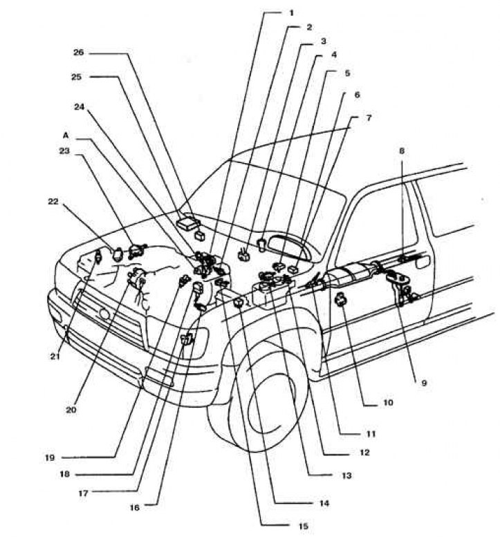
1. Throttle position sensor; 2. Recirculation system temperature sensor; 3. DLC3 connector; 4. Ignition switch; 5. Gasoline vapor pressure sensor; 6. Instrument panel; 7. Fuel pump relay; 8. Oxygen sensor 1; 9. Fuel pump; 10. N/P switch (on automatic transmission); 11. Oxygen sensor 2; 12. Vacuum distributor of the tank valve; 13. Vacuum distributor of the vapor pressure sensor; 14. Main injection relay (eFI marking); 15. Vacuum distributor of the recirculation valve; 16. Crankshaft speed sensor; 17. Knock sensor 1; 18. DLC1 connector; 19. Nozzle; 20. Camshaft rotation sensor (built into the ignition distributor); 21. Intake air temperature sensor; 22. Flow speed sensor; 23. Electronic ignition unit; 24. Liquid temperature sensor; 25. Processor unit (ECM); 26. Amplifier; A. Idle speed control
1996 3.4L V6 Emission Control and Fuel System Layout
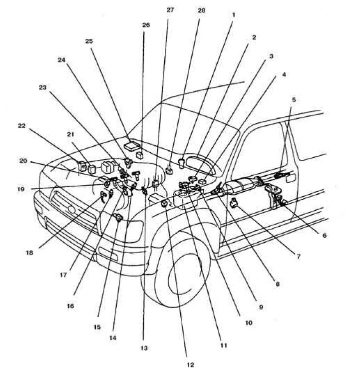
1. Ignition switch 2. Instrument cluster 3. Fuel vapor pressure sensor 4. Fuel pump relay 5. Oxygen sensor 2 6. Fuel pump 7. N/P switch (on automatic transmission) 8. Oxygen sensor 1 9. Vacuum distributor of the tank with absorber 10. Vacuum distributor of the vapor pressure sensor 11. Tank with absorber 12. Main injection relay (eFI marking) 13. Knock sensor 2 14. Knock sensor 1 15. Crankshaft speed sensor 16. 19. Injector 17. Fluid temperature sensor 18. Camshaft speed sensor 20. Ignition coil 21. Ignition module 22. Flow sensor 23. Idle air control valve 24. Throttle position sensor 25. Processor unit (ECM) 26. Amplifier 27. DLC1 connector 28. DLC3 connector
(The official source is on the portal: ToyotaMan.ru)
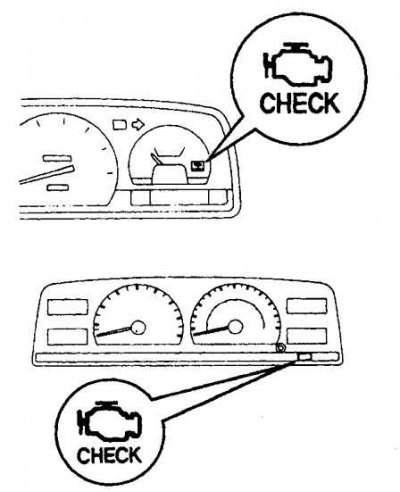
Variant of the location of the CHEK ENGINE indicator lamp on the instrument panel