
Attention! The models covered in this manual are equipped with an assisted restraint system (SRS), better known as «airbag system». To prevent accidental deployment of airbags, which could result in injury, be sure to deactivate the airbag system before working near components of the airbag system (see chapter 12).
1. These panels provide access to the various front panel mounting screws. Some panels use clips, while others are easily removed by prying with a screwdriver or trim remover. If you are going to remove the front panel, remove all panels.
2. Disconnect the ground wire from the battery (see paragraph 1 of chapter 5).
Lower instrument panel trim
3. On models with tilt steering, lower the steering column as low as possible.
4. Using a trim remover, gently pry the bottom of the panel away from the front panel until the latches are released. Do not scratch adjacent surfaces of the front panel (pic. 24.4). Disunite electric sockets of the switches established on the panel.
5. Installation is carried out in the reverse order of removal. Before finally locking the panel in place, make sure that the latches are securely engaged.
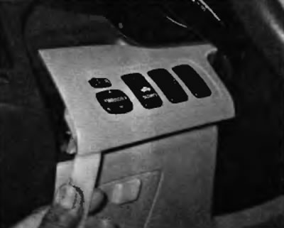
Pic. 24.4. Gently pry the bottom of the panel away from the front panel until the latches are released
Instrument panel bezel
6. Remove the lower instrument panel trim (see p.p. 3 and 4).
7. Using a trim remover, gently pry the bezel to release the tabs, then remove the bezel (pic. 24.7).
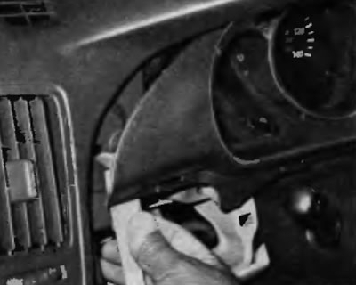
Pic. 24.7. Gently pry the bezel to release the clips and remove it
8. Installing is performed in the reverse order of removal. Before finally locking the panel in place, make sure that the latches are securely engaged.
Center panel trim audio unit and air conditioning control panel
9. Using a trim remover, gently pry the bezel to release the tabs, then remove the panel (pic. 24.9). Be careful not to scratch the surrounding surfaces of the left panel.
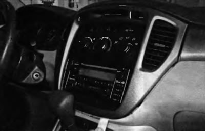
Pic. 24.9. Gently pry the bezel to release the latches and remove the panel
10. Installation is carried out in the reverse order of removal. Before finally fixing the panel in place, make sure that the fasteners are securely engaged.
Knee buffer
11. Remove the bottom trim panel of the instrument panel (see paragraphs. 3 and 4).
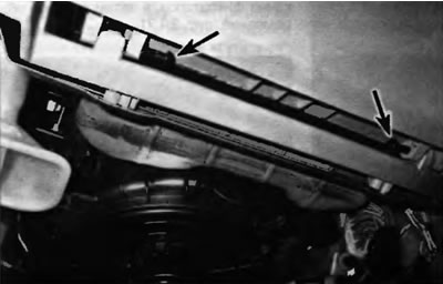
12. Remove the two fastening elements of the knee buffer cover (pic. 24.12).
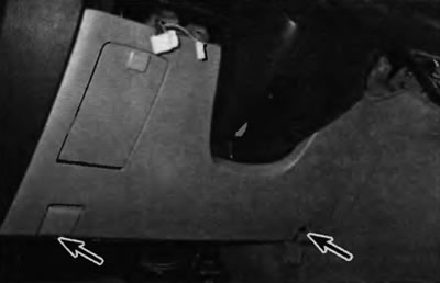
Pic. 24.12. Remove the two clips securing the buffer cover
13. Pull on the knee buff to disengage the clips behind it.
14. Unscrew the bolts of the knee buffer reinforcement, if necessary, to access the elements located under the front panel (pic. 24.14).
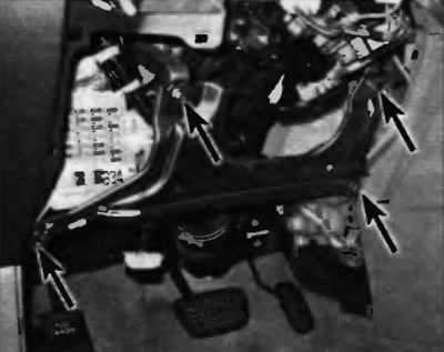
Pic. 24.14. Turn out bolts of fastening of strengthening of the knee buffer
Note. On models equipped with a driver's side lower airbag, refer to chapter 12.
15. Installation is performed in the reverse order of removal.
Storage compartment cover (compartments for gloves)
16. Remove the two clips at the bottom of the storage compartment cover and remove the cover (pic. 24.16).
Pic. 24.16. To remove the storage compartment cover, remove the two pins at the bottom of the cover
17. Installation is carried out in the reverse order of removal.
Stowage compartment trim panel (compartments for gloves)
18. Remove the cover of the storage compartment (see item 16)
19. Turn out screws of fastening of the panel of finishing and remove the panel (pic. 24.19).
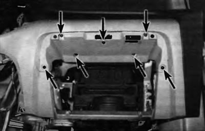
Pic. 24.19. Remove the screws securing the trim panel, and then remove the trim panel
20. Installation is carried out in the reverse order of removal.