



Raise the glass of the sliding/tilting roof panel and leave it in this position.
Adjusting the position involves removing the drive motor and moving the cables until the marks on the cables and the frame on both sides of the sliding and lifting roof panel are aligned. For further adjustments, do the following:
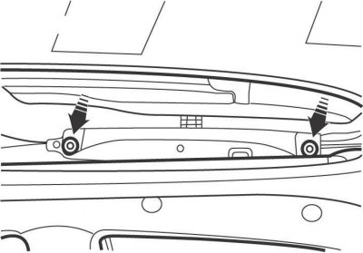
Figure 14.62. Screw locations (two screws are invisible) glass fastenings for the sliding and lifting roof panel
- remove 4 screws and remove the glass from the sliding/tilting roof panel (figure 14.62);
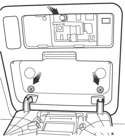
Figure 14.63. Location of upper console mounting screws
- remove the interior light and open the cover to access the roof sliding panel motor and unscrew the screws securing the upper console (figure 14.63);
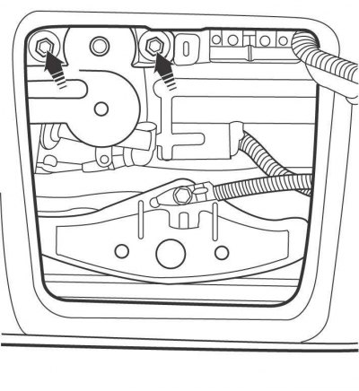
Figure 14.64. Location of the mounting screws for the sliding and lifting roof panel drive motor
- unscrew the screws and remove the motor, disconnecting it from the pulley with the cables of the sliding and lifting roof panel drive (figure 14.64);
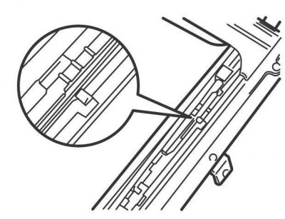
Figure 14.65. Alignment of marks on the cable and frame of the sliding roof panel
- move the end of the lift/slide roof panel drive cable until the marks on the cables and frame on both sides of the lift/slide roof panel are aligned (figure 14.65);
- after adjustment, install the roof sliding panel drive motor and the upper console;
- adjust the position of the front and rear sections of the sliding/tilting roof panel by loosening the glass securing screws and sliding it forward or backward to a distance that ensures a secure seal between the front and rear sections of the sliding/tilting roof panel and tightening the screws.