
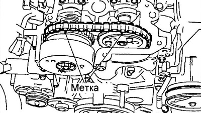
2. Set the piston of the first cylinder to the TDC of the compression stroke.
A) Rotate the crankshaft and align the mark on the pulley with the mark on the timing belt cover.
b) Make sure the marks on the timing sprockets point up as shown, otherwise turn the crankshaft one turn.
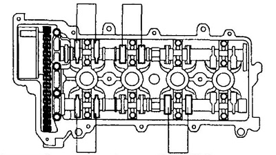
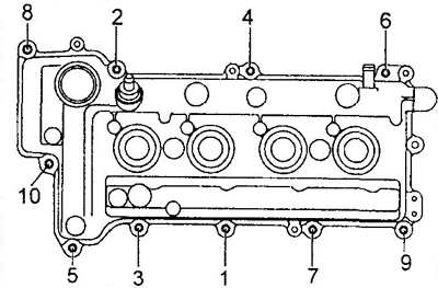
3. Using a feeler gauge, check the clearance in the actuator of the valves shown in the figure.
4. Turn the crankshaft one turn and check the clearance in the valve actuator shown in the figure.
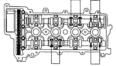
Nominal valve clearance:
- intake 0.18+0,055-0,035
- graduation 0.31+0,055-0,035
Note: Write down which valve clearance is not within specification.
5. If the backlash goes beyond the specified limits, remove camshafts and replace pushers with new, having adjusted a backlash.
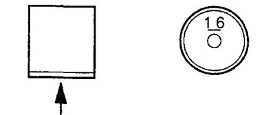
A) Determine the thickness of the removed pusher with a micrometer.
b) Calculate the thickness of the new tappet so that the clearance in the valve drive is within the recommended range.
N=T+ (A - B) mm
- N is the thickness of the new pusher,
- T is the thickness of the removed pusher,
- A is the measured clearance in this valve,
- B is the nominal gap.
Note: Pushrods are available in 29 sizes in 0.02mm increments and thicknesses from 5.12mm to 5.68mm. The designation of the thickness of the pusher is embossed on its inner side.
V) Apply engine oil to the circumference of the tappets and install them into the tappet holes.
Note: after installation, make sure the pushrods rotate freely.
6. Install camshafts.
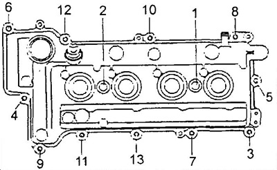
7. Install the cylinder head cover.
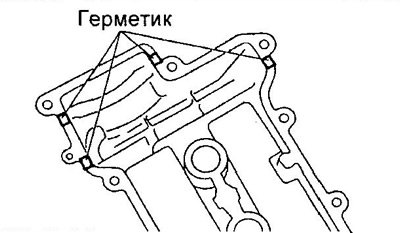
A) Apply sealant to the cylinder head cover at the locations shown in the illustration.
Sealant: Three Bond TB 1280E or equivalent.
b) Install the cover and tighten its fasteners.
Torque:
- cap nut - 7 -11 Nm
- nut - 9 - 13 Nm
8. Installing the ignition coil.
- Tightening torque - 6-9 Nm
9. Install the air filter.