
Turn off the ignition, disconnect the wire «masses» from the battery and wait 2 minutes before carrying out further work.
Set the wheels to drive straight ahead.
Remove the steering wheel, then turn the ignition key to the LOCK position to block the steering shaft from rotating, otherwise the airbag coil wire may be damaged.
Remove the lower trim panel, under the steering column.
Remove the steering column covers.
Disconnect the electrical connectors from the steering column wiring harness.
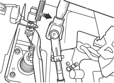
Pic. 13.7. An arrangement of a coupling bolt of fastening of a steering shaft to the universal joint
Mark the position of the universal joint in relation to the steering shaft and remove the pinch bolt (pic. 13.7).
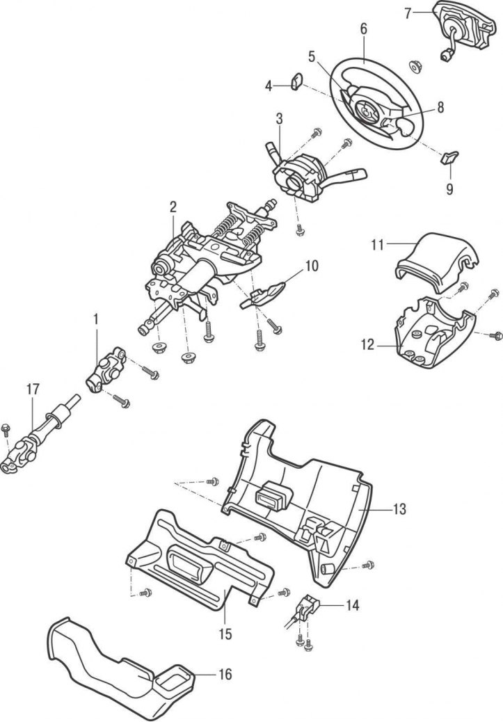
Pic. 13.8. Steering column: 1 - universal joint; 2 - steering column; 3 - combined switch; 4 – a cover No. 2 of a steering wheel; 5.8 - Torx screws; 6 - steering wheel; 7 - airbag; 9 - cover No. 3 of the steering wheel; 10 – a protective plate of a steering column; 11 – the top casing of a steering column; 12 – the lower casing of a steering column; 13 – the lower upholstery of the panel of devices; 14 - handle for opening the hood lock; 15 - air duct; 16 - lower insert of the instrument panel; 17 - intermediate shaft
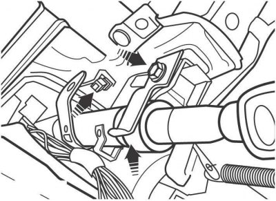
Pic. 13.9. The location of the steering column mounting bolts on models from 2001
Remove the steering column mounting bolts, then lower and pull back to make sure nothing is holding it down (pic. 13.8, 13.9). Separate the intermediate shaft from the steering shaft and remove the steering column.
Install the steering column as follows:
Insert the lower end of the steering shaft into the intermediate shaft universal joint socket and screw in, but do not tighten, the steering column mounting bolts.
Tighten the steering column mounting bolts to 25 Nm.
Screw in the coupling bolt securing the universal joint to the steering shaft and tighten it to a torque of 26 Nm (see fig. 13.7).
Further installation is carried out in the reverse order of removal.