
Removing
1. Remove the steering wheel pad
A) Loosen the bolt.
b) Remove the trim and disconnect the connector.
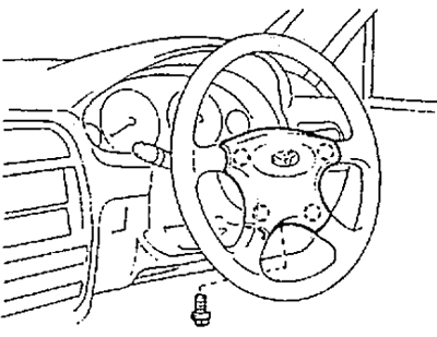
(For vehicles equipped with an airbag)
Remove the steering wheel cover.
Attention: store the steering wheel pad face up.
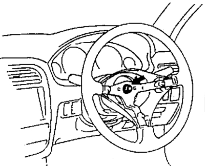
2. Remove the steering wheel.
A) Loosen the nut. Mark the main shaft and steering wheel.
- Tightening torque - 35 Nm
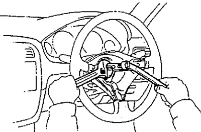
b) Using the special tool, remove the steering wheel.
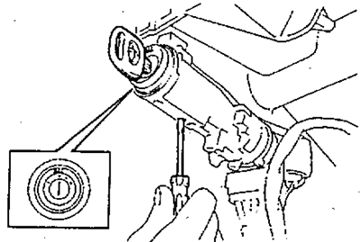
3. (2C, manual transmission)
Disconnect the idle speed control lever when the diesel engine is warm.
A) Using a screwdriver, remove the idle speed control knob as shown in the figure.
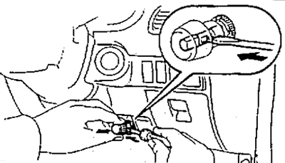
b) Using a mandrel, drown the lever.
4. Disconnect the hood lock lever.
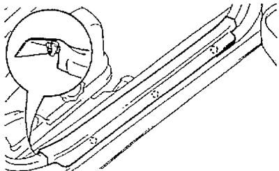
5. Remove finishing of a threshold of a forward door.
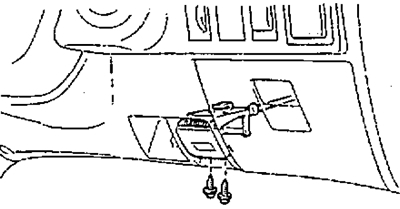
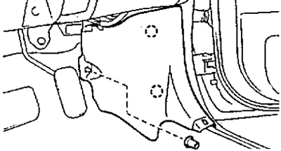
6. Remove the side trim.
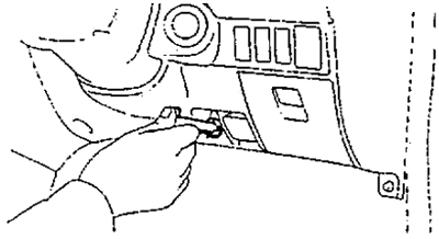
7. Remove the bottom finishing panel from the driver's side.
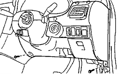
8. Remove air duct #1.
9. Remove air duct #2.
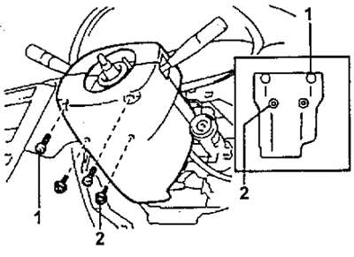
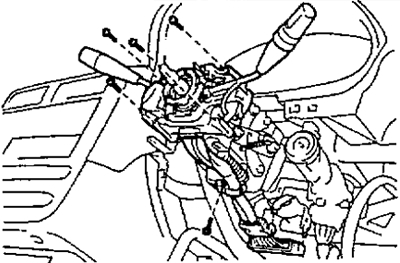
10. Turn away screws of fastening and remove casings of a steering column.
Models without tilt adjustment
Tilt Models
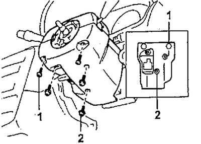
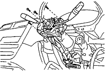
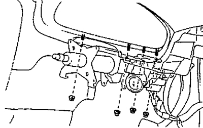
11. Turn away screws of fastening, disconnect a socket and remove the combined switch.
Models without tilt adjustment
Tilt Models
12. (Tilt Models)
Loosen the bracket bolt.
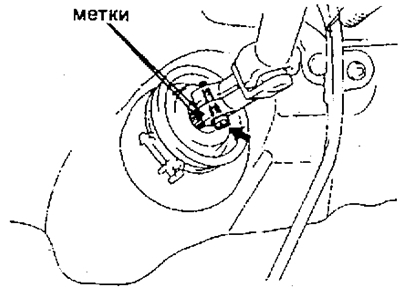
13. Disconnect the universal joint.
(Models without tilt adjustment)
A) Mark the worm and universal joint.
b) Loosen the bolt and disconnect the universal joint from the worm.
- Tightening torque - 36 Nm
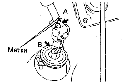
(Tilt Models)
A) Remove the bolt "A".
- Tightening torque - 36 Nm
b) Loosen the bolt "IN".
- Tightening torque - 36 Nm
V) Mark the steering column main shaft and universal joint, and disconnect the joint from the shaft.
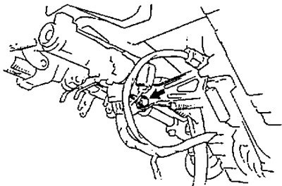
14. Remove the ignition lock cylinder from the bracket.
A) Set the ignition key to position "ACC".
b) Press the locking pin with a thin rod or screwdriver and remove the lock cylinder.

15. Turn away nuts of fastening and remove a steering column in gathering.
Attention: when installing, first tighten the fastening nuts, then connect the universal joint by aligning the marks, and only then tighten the nuts.
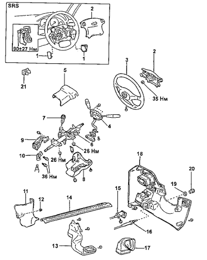
Removing the steering column
1 - bottom cover of the steering wheel,
2 - steering wheel pad,
3 - steering wheel,
4 - combined switch assembly,
5 - the upper casing of the steering column,
6 - steering column assembly,
7 - ignition lock cylinder,
8 - the lower casing of the steering column,
9 - bracket (angle adjustable models),
10 - universal joint,
11 - side trim,
12 - latch,
13 - air duct No. 1,
14 - trim front door sill,
15 - hood lock lever,
16 - idle speed adjustment lever when the diesel engine is warming up (2C, manual transmission),
17 - air duct No. 2,
18 - lower trim panel on the driver's side,
19 - idle speed adjustment lever nut (2C, manual transmission),
20 - handle of the idle speed adjustment lever (2C, manual transmission),
21 - cover (models without ignition switch illumination).
Installation
Installation is carried out in the reverse order of removal. When installing, align the marks made when removing.