
Warning! Clutch operation generates dust containing asbestos, which is harmful to health, so when cleaning the clutch, do not use compressed air or inhale the dust. Remove dust from clutch parts using brake cleaner or methyl alcohol, then wipe dry.
Removing the clutch disc produce as follows:
Remove the clutch slave cylinder and secure it to the body with a soft wire without disconnecting the tube from it.
Remove the gearbox. The fork and release bearing may remain installed on the gearbox.
To support the clutch disc during removal, install a special mandrel or the old transmission input shaft in the disc hub.
Mark with a marker or paint the position of the clutch assembly in relation to the flywheel.
Using a special tool or a screwdriver, use the teeth of the flywheel ring gear to block it from turning.
Gradually loosen the clutch assembly mounting bolts diagonally by turning each bolt half a turn until the spring action stops and the bolts can be loosened by hand.
Remove pressure plate.
Remove the clutch disc with a special mandrel.
Checking the condition of the clutch disc produce as follows:
Check the condition of the friction surface of the flywheel for cracks, burn marks and surface wear.
Check the flywheel runout, for which:
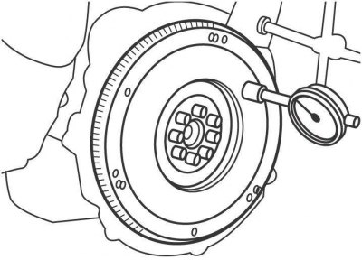
Pic. 8.3. Flywheel Runout Measurement
- install a bracket with a dial indicator on the engine block so that the measuring tip of the indicator rests against the end of the flywheel (pic. 8.3);
- set the indicator to 0;
- turn the engine crankshaft and record the maximum and minimum values on the indicator;
- the difference between these values is the runout of the flywheel, which should be no more than 0.1 mm.
Check the condition of the friction linings of the clutch driven disk and if they have traces of oil or mechanical damage, replace the driven disk.
Check the thickness of the clutch disc lining, which should protrude at least 0.8 mm above the rivet heads. If their thickness is less than acceptable or if the rivet heads are close to the working surface, replace them or the clutch disc.
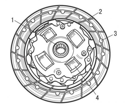
Pic. 8.4. Places for checking the clutch disc: 1 - slots in the hub; 2 – lining thickness; 3 - rivets; 4 - springs
Check that the springs are not broken or cracked. Check the condition of the splines in the clutch disc hub for wear (pic. 8.4).
The clutch disc should slide easily and smoothly on the splines of the gearbox input shaft. If the clutch disc is being replaced, the clutch release bearing must also be replaced.
Check the condition of the release bearing. A defective clutch release bearing can be determined without removing it from the vehicle, for which, while the engine is running, press the clutch pedal. If there is noise when the clutch pedal is depressed, the clutch release bearing is defective and needs to be replaced.
Check the condition of the clutch pressure plate.
Check the tightness of the spring connection between the pressure plate and the clutch cover. No scratches, missing or damaged rivets are allowed.
Check the pressure plate for cracks, burn marks and surface wear.
Installing the clutch disc produce as follows:
Note. When installing a new clutch disc or pressure plate, remove the anti-corrosion protection from them.
Attention! When installing the driven disc, make sure that even small amounts of oil do not get on its friction linings. Therefore, before installation, wipe the mating surface of the flywheel and the surface of the pressure plate with a clean rag. Install the driven disc with clean hands.
Lubricate the splines in the driven disc hub with a thin layer of special grease based on molybdenum disulphide.
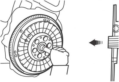
Pic. 8.5. Installation position of clutch disc (arrow points to flywheel)
Install the driven disc with centering mandrel on the flywheel so that the protruding part of the hub of the disc with springs is directed outward, towards the gearbox (pic. 8.5).
Install the clutch assembly, lining up the holes in the clutch housing with the flywheel guide pins. When reinstalling a previously removed clutch pressure plate, check that the marks made before removal are aligned.
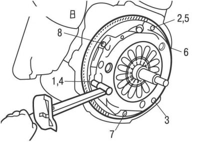
Pic. 8.6. Clutch cover bolt tightening sequence
Gradually, in the sequence shown in Figure 8.6, tighten the clutch cover mounting bolts to a torque of 19 Nm.
Remove the mandrel from the driven disk.
Lubricate the gearbox input shaft spline and the clutch release bearing guide bushing with a thin layer of special grease based on molybdenum disulphide.
Install the clutch release bearing.
Install the gearbox.
Install the clutch slave cylinder.