
Removing
When removing, pay attention to the following operations:
1. Remove the gearbox.
2. Remove the cover and clutch disc.
A) Mark the clutch cover and flywheel.
b) Loosen each set screw one turn to ensure that the spring is evenly released from the preload.
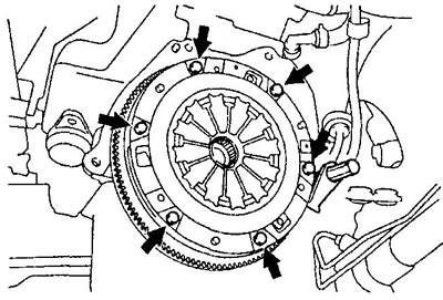
V) Remove all set screws and remove clutch cover and clutch disc from engine flywheel.
3. Remove the clutch release fork and release bearing.
A) Remove the bracket and remove the release bearing.
b) Remove the clutch release fork.
Installation
Note: Install in the reverse order of removal.
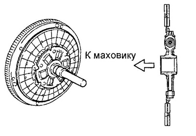
1. Using a centering mandrel, install the clutch disc.
Note: Do not confuse the drive installation direction.
2. Install the clutch cover.
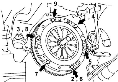
A) Align the previously applied alignment marks on the casing and flywheel.
b) Tighten the mounting bolts in the order shown in the figure.
- Tightening torque - 19 Nm
Note:
- Tighten the bolts in several stages.
- Slightly move the centering mandrel to make sure the disc is centered.
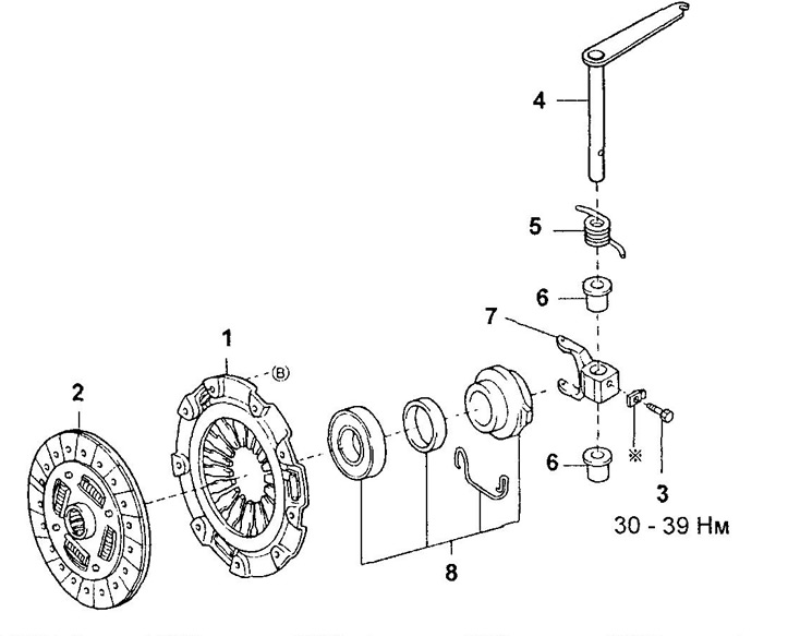
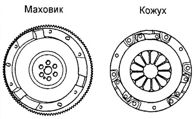
Clutch.
1 - clutch cover,
2 - clutch disc,
3 - bolt,
4 - clutch fork lever,
5 - spring,
6 - bushing,
7 - fork,
8 - release bearing assembly.
3. Check the relative position of the petals of the diaphragm spring.
- Maximum deviation from the plane - 0.7 mm
If the deviation exceeds the allowable value, use a special tool to adjust the relative position of the ends of the spring petals.
Examination
1. Using a vernier caliper, measure the rivet depth from the lining surfaces.
- Minimum depth - 0.3 mm
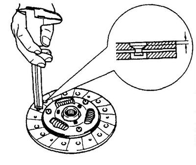
If the depth is less than acceptable or the disc wear is uneven, replace the clutch disc.
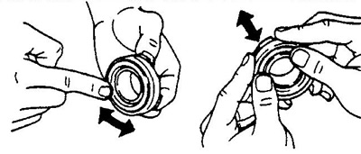
2. Rotate the bearing by hand and apply force to it in the axial direction. Replace the bearing if it sticks or is difficult to turn.
Note: The release bearing is lubricated for life and does not require cleaning or lubrication.
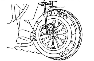
3. Using a dial gauge, check the flywheel runout.
- The maximum allowable runout is 0.1 mm
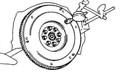
If the measured runout exceeds the maximum allowable value, replace the flywheel.