



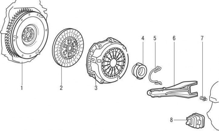
Figure 8.1. Clutch: 1 – flywheel; 2 – clutch disc; 3 – pressure plate; 4 – clutch release bearing; 5 – locking spring; 6 – clutch release fork; 7 – stud with ball pin; 8 – protective cover
All models are equipped with a dry single-plate clutch, which consists of a driven and pressure plate, a central diaphragm spring, a casing and a clutch release bearing (figure 8.1).
The driven clutch disc moves freely on the splines of the input shaft of the gearbox and is clamped between the flywheel and the pressure plate by the force created by the central diaphragm spring. Friction linings are riveted to both sides of the driven disk. The driven clutch disc is connected to the hub through the torsional vibration damper components. The need for a torsional vibration damper is caused by the following.
When the vehicle's speed changes abruptly, when it hits uneven road surfaces, when the clutch is suddenly engaged, or as a result of uneven engine operation, dynamic loads arise in the vehicle's transmission, causing twisting (unwinding) transmission shafts. Uneven engine torque can cause significant overloads in the transmission due to the occurrence of torsional vibrations and resonance when the frequencies of the transmitted loads coincide with the natural frequencies of the transmission. Elastic vibrations of the transmission lead not only to the occurrence of noise in mechanisms and units, but also to dangerous vibrations, and sometimes to breakdowns of parts when the amplitude of vibrations reaches a large value. A damper is required to absorb the energy of torsional vibrations.
The clutch release drive is hydraulic. The clutch release bearing is mounted on the front side of the gearbox on the clutch release sleeve. The bearing is moved by the clutch release fork. When you press the clutch pedal, the piston in the master cylinder moves and compresses the fluid, which flows through the hose into the clutch slave cylinder. Under pressure, the piston of the clutch slave cylinder moves and activates the clutch release fork. The clutch release fork moves the bearing, which acts on the pressure plate spring and moves the pressure plate away from the driven disc of the clutch. The clutch is adjusted automatically.
Before replacing components that are clearly faulty, perform the following preliminary checks to diagnose a faulty clutch and its drive:
Check the brake fluid level in the brake fluid reservoir, which also serves as a reservoir for the clutch hydraulic drive.
If the level is below the required level, add fluid and check the hydraulic system for brake fluid leaks.
With the engine idling and the gearshift lever in neutral, press the clutch pedal and after a few seconds engage any gear; no noise should be heard from the gearbox. If there is increased noise when engaging a gear, the pressure plate and/or clutch disc may be defective.
To check that the clutch is fully disengaged, start the engine, apply the parking brake, press the clutch pedal so that it is 10–15 mm from the floor, and engage and disengage first gear several times. If the gear is difficult to engage, check the clutch master cylinder pushrod stroke and the brake fluid level in the reservoir.
Visually inspect the clutch pedal bushing, located at the top of the pedal, for excessive play or binding.
From underneath the vehicle, check that the clutch release fork is installed on the stud with the ball pin.