
- air intake system with adjustable geometry (ACIS),
- catalytic converter, intelligent electronic accelerator control system (ETCS-i),
- vapor recovery system (EVAP),
- forced crankcase ventilation system (PCV),
- sequential electronic fuel injection system (SFI),
- intelligent variable gas distribution system (VVT-i).
This chapter describes the general design, inspection procedures within the purview of a lay mechanic, and replacement procedures for components used in each of the systems listed above (if possible). In addition, you will find a general description of all sensors and output actuators used in the engine management system, including the purpose, location and a brief description of the principle of operation of each element (see paragraph 2). A description of the procedures for replacing sensors and actuators is also included.
Before deciding that any emission control system is malfunctioning, carefully check the fuel and ignition systems. The diagnosis of many emission control devices requires the use of special tools, equipment and knowledge. If any service procedure is not described in this book or outside of your area of expertise, consult your dealer's or other service center's service department. But keep in mind that the most common cause of problems in emission control systems is the simplest loosening of an electrical connector, a broken wire, or a disconnected vacuum hose. Therefore, first check the hoses, wiring and connections.
However, emission control systems are not very difficult to maintain and repair. You can perform many checks and most routine maintenance tasks quickly and easily on your own using the usual set of inspection and adjustment tools.
Application. Since in many cases components of emission control systems are covered by warranties, please check with your dealer for warranty coverage before using these systems. After the warranty period has expired, you may choose to perform some of the cell inspection and/or replacement procedures described in this chapter to save money.
Pay particular attention to any special precautions highlighted in this chapter. It should be noted that the drawings depicting the various systems may not exactly match the system installed on your vehicle due to the inevitable improvements made to the design during the manufacturing process.
Emission reduction system information plate (VECI) (pic. 1.6, a) attached to the underside of the hood. This plate contains important information on emission reduction systems and adjustments. On another plate with a wiring diagram for vacuum hoses (pic. 1.6, b) contains a corresponding scheme with the designation of elements of systems for reducing the level of harmful emissions. When servicing the engine or emission control systems, be sure to refer to the VECI and vacuum hose wiring labels on your vehicle for the latest information.

Pic. 1.6, a. On the emission reduction label (VECI) contains important information such as the type of emission reduction systems installed on the engine and some information on settings
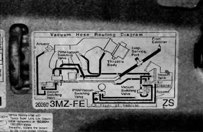
Pic. 1.6, b. Typical vacuum hose wiring for a V6 model