



Gear Locking System Parts
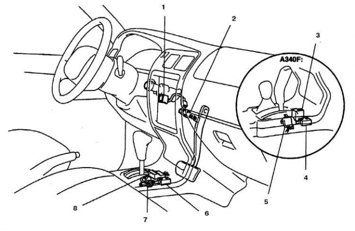
1. Key lock solenoid; 2. Brake light switch; 3, 8. Processor unit of the fixation system; 4, 6. Locking solenoid; 5, 7. Limit switch
Checking and replacing parts
1. Remove the lower left trim panel and steering wheel trim (see subsection 10.23).
2. Find the parts of the locking system (see fig. Gear locking system parts).
Shift Lock Solenoid
3. Disconnect the connector from the solenoid.
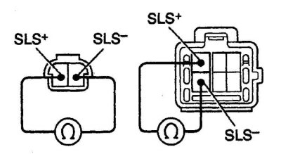
4. Measure the resistance between the specified terminals. If the resistance is not normal, or there is no click when the terminals are energized, replace the solenoid.
Key lock solenoid
5. Disconnect the connector from the solenoid.
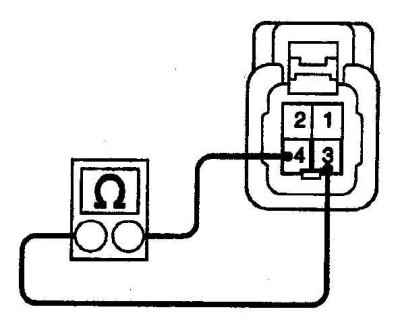
6. Measure the resistance between the specified terminals. If the resistance is not normal, or there is no click when the terminals are energized, replace the solenoid.
Limit switch
7. Disconnect the connector from the switch.
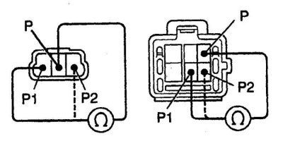
8. Measure the resistance between the indicated terminals. If there is no circuit between the indicated terminals, replace the switch.
Limit Switch Test Table
| Selector position | Verifiable findings | Set value |
| 1P | P1 – P | Closed circuit |
2P | P1 – P | Closed circuit |
| 7 – 1 | ||
| P2 – P | ||
| R, N, D, 2, L | P2 – P | Closed circuit |