
Attention! Wait until the engine has completely cooled down before proceeding with the procedures! See also the warning at the beginning of the Section Depressurizing the supply system.
Attention! If the stereo system installed in the car is equipped with a security code, before disconnecting the battery, make sure that you have the correct combination to activate the audio system!
Throttle body
Examination
1. Check the smoothness of the throttle valve.
2. Start the engine, disconnect all vacuum hoses and, using a vacuum gauge, measure the depth of vacuum at each of the throttle body ports at idle and engine speed of 3500 rpm. Compare the measurement results with the requirements of regulatory maps.
Replacement
Details of installation of the throttle body on engines 2UZ-FE
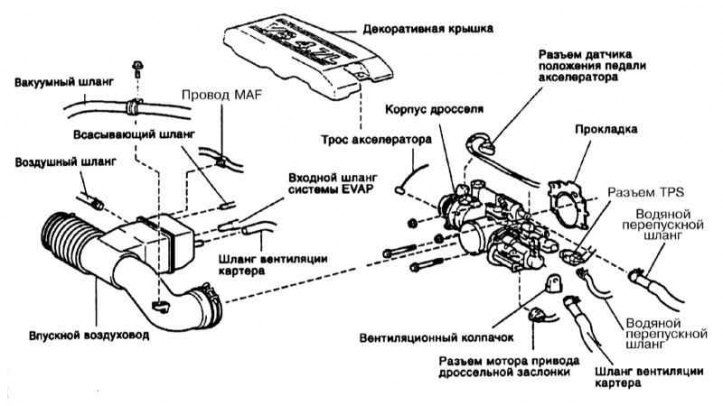
The device of the throttle body on 2UZ-FE engines is somewhat original. The drive cable performs only a preliminary function. Electronic throttle control. Throttle position sensor mounted on the throttle body (TPS), which informs the ECU of its current position. The voltage at the VTA and VTA2 terminals of the ECU varies from 0 to 5 V in proportion to the throttle opening angle. At the same time, the ECU, comparing the received signal with signals from other sensors, instructs the electric motor with a magnetic clutch of the throttle actuator to correct its position (if necessary) according to the requirements of the driver's foot». If any of the elements of the electronic throttle control fails, it is driven only by means of a pedal and a cable, and closing is carried out by means of a return spring. The system requires care when handling it. Do not strike or drop the system under any circumstances. Care is also required when handling electrical connections.
1. Remove acoustic/decorative engine cover (refer to illustration above).
2. Drain the coolant.
3. Remove the top part of the inlet pipeline.
4. Disconnect the accelerator cable from the throttle body.
5. Disconnect the electrical connector from the TPS.
6. Disconnect the throttle control motor electrical connector.
7. Disconnect the accelerator pedal position sensor connector.
8. Disconnect the sensor wiring from the two clamps on the wiring bracket
9. Disconnect the crankcase ventilation hose and water bypass hose from the throttle body.
10. Remove the vent cap. Give two bolts and two nuts and remove the throttle body from the inlet pipeline. Disconnect the water bypass hose from the thermostat on the throttle body and remove the throttle body from the engine. Remove the gasket.
11. Installation is carried out in the reverse order. Install a new throttle body gasket. Make sure that the fixing bolts and nuts are tightened to the required torque. Fill with coolant. Start the engine and check for leaks.
Fuel pressure control
Replacement
Fuel pressure regulator design
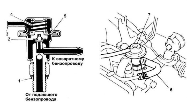
1 - O-ring; 2 - Valve; 3 - Vacuum control hose; 4 - Spring; 5 - Diaphragm
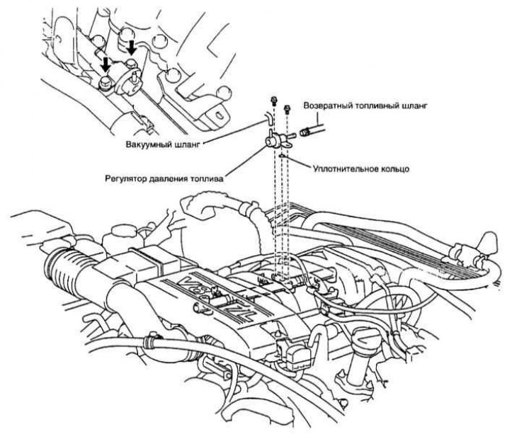
Fuel pressure regulator installation diagram
1. Relieve the pressure in the supply system (see Section Depressurizing the supply system) and disconnect the negative cable from the battery.
Attention! If the stereo system installed in the car is equipped with a security code, before disconnecting the battery, make sure that you have the correct combination to put the equipment into operation!
2. The installation diagram and design of the fuel pressure regulator are shown in the illustrations above. Disconnect the vacuum hose from the pressure regulator.
3. Place a drain container under the fuel return hose, or wrap it with a rag.
4. Squeeze the clamp and disconnect the fuel return hose from the pressure regulator.
5. On V8 models, back off the locknut and remove the regulator from the O-ring.
6. Don't forget to replace the o-ring and make sure the regulator is properly seated on the line. Further installation is carried out in the reverse order of the dismantling of the components.
Fuel line and injectors
Examination
See the description of the procedure for checking the injection system in Section Check of serviceability of functioning of system of electronic injection.
Replacement
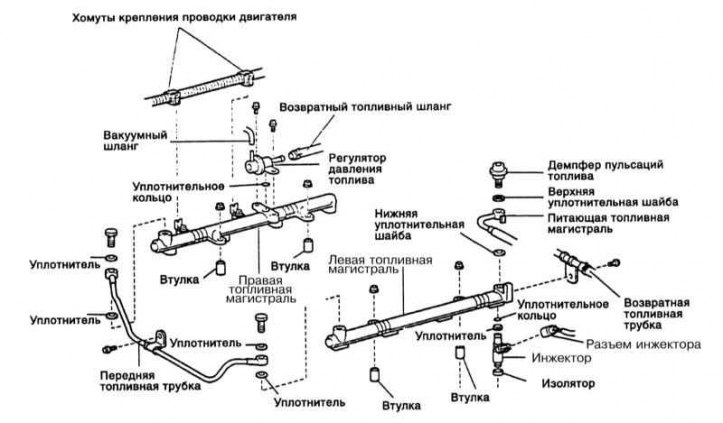
Fuel Injection System Components
1. Relieve the pressure in the supply system (see Section Depressurizing the supply system) and disconnect the negative cable from the battery.
Attention! If the stereo system installed in the car is equipped with a security code, before disconnecting the battery, make sure that you have the correct combination to put the equipment into operation!
2. Remove the throttle body cover and upper intake manifold (see chapter Engine).
3. In preparation for spilling fuel, remove the fuel pulsation damper, top gasket, and fuel lines (refer to illustration above).
4. Remove the accelerator cable and give two fastening nuts from the bracket (see Section Removing, installing and adjusting the accelerator cable).
5. Remove the hose from the PCV valve.
6. Disconnect the electrical connector from the EVAP solenoid valve. Disconnect the accelerator cable clamp and remove the EVAP solenoid valve from the intake manifold.
7. From an arm of a cover of the case of a throttle disconnect a diagnostic socket DLC1, then turn out a bolt and remove an arm.
8. Tag and disconnect the engine wiring clamps from the brackets.
9. Give a bolt of fastening of a collar on a returnable fuel tube to the left part of a fuel highway. Remove the bolts from the front (transitional) fuel pipe.
10. Hang identification labels on contact sockets of each of injectors. Disconnect the wiring from the injectors and move the harness to the side.
11. Give four nuts of fastening of fuel highways to the bottom part of the inlet pipeline.
12. Remove fuel highways together with injectors, four remote plugs and eight insulators. Be careful. The injectors are held only by O-rings; when removing the fuel lines, do not drop the injectors.
13. Install seals on all injectors, lubricate new sealing rings with gasoline and install them on injectors.
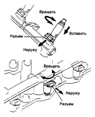
14. Slightly rotating the injector left and right, insert it into the socket on the fuel line (refer to accompanying illustration). Install all injectors in this way.
15. Establish fuel highways by sockets of injectors up.
16. Install new insulators and bushings in their places on the inlet pipeline. Fit the bolts securing the fuel lines to the intake manifold.
17. Make sure the injectors can rotate. If the injector «stuck», check the position of the O-ring or replace it.
18. Connect the injector connectors according to the attached tags.
19. Further installation is carried out in the reverse order. make sure that all fasteners are tightened to the required torque.
20. Start the engine and check for leaks.