
Front axle
Removing
Attention! If the vehicle is equipped with electronically controlled air suspension, turn off the suspension height control switch.
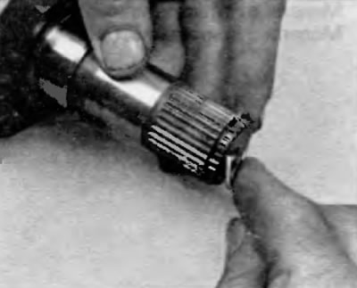
1. Remove the wheel cap or hub cap. Knock out the caulking of the nut with a center punch or chisel (pic. 2.1).
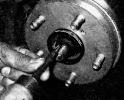
Pic. 2.1. If the axle shaft nut is locked by punching, knock down the caulking with a punch (wheel removed for clarity)
2. Loosen the hub nut using a socket and large extension (pic. 2.2).
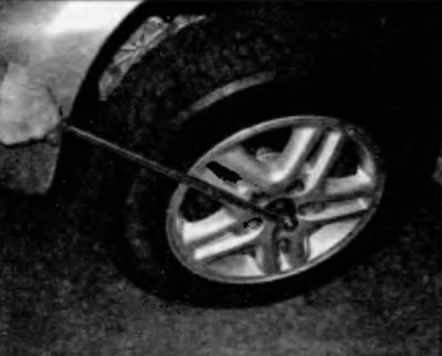
Pic. 2.2. Loosen the axle shaft/hub nut with a lever of sufficient length
3. Loosen the wheel nuts, raise the vehicle and place secure supports under it. Remove the wheel. Drain the gearbox oil (see chapter 1).
4. Turn away nuts and turn out a bolt of fastening of the spherical joint to the cross-section lever, and then wring out the cross-section lever down and separate the lower cross-section lever from the ball joint (see chapter 10). Now loosen the axle/hub nut.
5. Turn the swing arm away from the vehicle until the end of the axle shaft is released from the hub.
Note. If the axle pins are sticking in the hub bore, tap the end of the axle with a plastic mallet. Hang the outer end of the axle shaft with a piece of wire to avoid unnecessary deformation of the inner CV joint.
6. If you are working with the right half shaft on a model with a four-cylinder engine, remove the intermediate support mounting bolts. If you are working on a V6 model, use special pliers to remove the circlip from the intermediate shaft intermediate bearing.
7. Gently pry and remove the inner end of the half shaft (or, depending on the model, intermediate shaft) from a gearbox in a block with a drive axle. To do this, place a large screwdriver or pry bar between the gearbox or intermediate support and the CV joint (pic. 2.7). Support the CV joints and carefully remove the axle shaft from the vehicle.
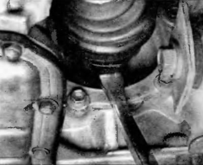
Pic. 2.7. To remove the inner end of the axle shaft from the gearbox, pry off the CV joint housing with a large screwdriver or pry bar
Installation
8. Remove the retaining ring from the inner end and install a new one (Figure 2.8, a, b). Lubricate the boot of the differential or intermediate shaft with multipurpose grease and raise the axle shaft to the required height while supporting the CV joints.
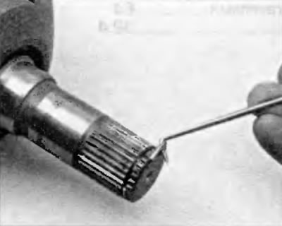
Pic. 2.8, a. Using a small screwdriver or an awl, remove the circlip from the inner end of the shaft
Ryas. 2.8b. To install a new retaining ring, insert one end of the ring into the groove and gradually insert the entire ring into the groove
9. Insert the splined end of the inner CV joint or countershaft into the differential side gear and make sure that the circlip locks into the appropriate groove. If you are installing the axle shaft/countershaft, install the intermediate bearing mounting bolts or install the circlip, as applicable.
10. Apply a light coat of multipurpose grease to the splines of the outer CV joint, move the steering knuckle assembly to the side with the suspension strut, and insert the axle shaft into the hub.
11. Connect the ball joint to the lower transverse arm and tighten the nuts (see tightening torques in chapter 10).
12. Screw on a new axle shaft/hub nut. Tighten the hub nut securely, but do not attempt to tighten it to the actual torque prescribed until the vehicle is completely lowered.
13. Grab the inner CV joint housing (not for the axle) and pull outward to ensure that the axle shaft is securely locked into the gearbox. If the inner CV joint-to-flange bolts have been loosened, tighten them to the specified torque listed in the Specifications at the beginning of this chapter.
14. Install the wheel, tighten the wheel nuts and lower the vehicle.
15. Tighten the wheel lug nuts to the specified torque given in the Specifications at the beginning of this chapter. Tighten the hub nut to the specified torque given in the Specifications at the beginning of this chapter. Using a center punch and a hammer, lock the nut by punching into the groove on the axle shaft.
16. Fill the gearbox with the recommended transmission fluid in the prescribed amount (see chapter 1).
Rear axle (4WD models)
Removing
Attention! If the vehicle is equipped with electronically controlled air suspension, turn off the suspension height control switch.
17. Remove the wheel cap or hub cap. Knock out the caulking of the nut with a center punch or chisel (pic. 2.1).
18. Loosen the hub nut using a socket and large extension (pic. 2.2).
19. Loosen the wheel nuts, raise the car and place reliable supports under it. Remove the wheel.
20. Remove the ABS sensor wire clamps and parking brake cable bracket from the trailing arm.
21. Turn out bolts of fastening of cross-section levers to a support of a nave (see chapter 10).
22. Turn away a nut of a half shaft, and then extend a half shaft from a support of a back nave. Be careful not to damage the sealing lip of the rear hub support inner seal. If the splines on the outer CV joint shaft sink into the splined hole in the hub, release the CV joint shaft with a hammer and punch.
Warning. Do not let the axle shaft hang on the inner CV joint.
23. Gently pry and remove the inner end of the axle shaft from the differential. To do this, place a large screwdriver or pry bar between the differential and the CV joint housing. Support the CV joints and carefully remove the axle shaft from the vehicle.
Installation
24. Remove the retaining ring from the inner end and install a new one (pic. 2.8, a, b). Lubricate the boot of the differential or intermediate shaft with multipurpose grease and raise the axle shaft to the required height while supporting the CV joints.
25. Insert the splined end of the inner CV joint or countershaft into the differential and make sure the circlip locks into its groove.
26. Apply a light coat of multipurpose grease to the splines of the outer CV joint, push the rear hub support aside and insert the axle shaft into the hub.
27. Connect the transverse arms to the rear hub support (see «Tightening torques for threaded connections» in chapter 10).
28. Screw in a new axle shaft/hub nut. Tighten the hub nut securely, but do not attempt to tighten it to the actual torque prescribed until the vehicle is completely lowered.
29. Grab the inner CV joint housing (not for the axle) and pull outward to ensure that the axle shaft is securely locked into the rear axle.
30. Install the wheel, probably the wheel nuts and lower the car.
31. Tighten the wheel nuts to the specified torque as specified in Specifications at the beginning of chapter 1. Tighten the hub nut to the specified torque specified in Specifications at the beginning of this chapter. Using a center punch and a hammer, lock the nut by punching into the groove on the axle shaft.
32. Fill the rear axle with the recommended gear oil in the prescribed quantity (see chapter 1).