
Examination
Attention! If the vehicle is equipped with electronically controlled air suspension, turn off the suspension height control switch.
1. Raise the rear of the vehicle and place secure supports under it. Install wheel chocks under the front wheels to prevent the vehicle from rolling off the stands. Release the parking brake and place the transmission in neutral.
2. Crawl under the car and visually inspect the propeller shaft. Look for any dents or cracks. If there are any, the driveshaft should be lured.
3. Weld for oil leakage at the front and rear ends of the propeller shaft. A leak in the connection between the propeller shaft and the transfer case indicates a failure of the transfer case seal. A leak at the junction of the propeller shaft with the rear differential indicates a failure of the cuff of the drive gear.
4. Remaining under the vehicle, have an assistant turn the rear wheel to start turning the driveshaft. When performing this operation, make sure that the universal joints work properly, i.e. bases of sticking, noise or excessive play. Listen for the possible appearance of noise coming from the intermediate support. If present, this indicates wear or damage to the support. Also check the rubber section of the intermediate support for cracks or separating from the metal.
5. Cardan joints can also be welded when the cardan shaft is stationary. To do this, grasp both sides of the hinge and try to twist the hinge. Any play in the hinge is a sign of significant wear. The ability to raise the shaft also indicates the presence of play in the universal joints. If the joints are worn, replace the front or rear sections of the propeller shaft as a single assembly.
6. Finally, check the tightness of the propeller shaft fastening bolts at its ends.
Removal and installation
Attention! If the vehicle is equipped with electronically controlled air suspension, turn off the suspension height control switch.
7. Raise the rear of the vehicle and place secure supports under it. Place wheel chocks under the front wheels to prevent the vehicle from rolling off the stands. Release the parking brake and place the transmission in neutral.
8. Apply reference marks (in front of each other) on the flange of the cardan shaft and the flange of the differential drive gear (pic. 4.8). This should make it easier to reset the driveshaft to its original position relative to the differential and thus keep the shaft balanced.
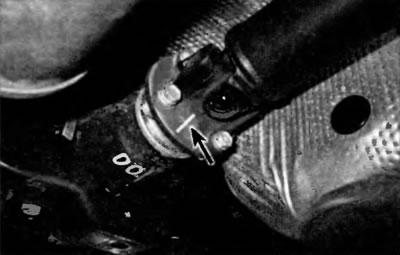
Pic. 4.1. Mark the mutual position of the cardan shaft and the flange of the drive gear of the differential. Then with two wrenches (one to hold) remove all four screws
9. Turn out bolts of the back universal joint. Rotate the propeller shaft if necessary (or wheels), to bring the bolts into the most accessible position for working with them. Remove the four bolts, nuts and washers.
10. Mark the position of the intermediate supports, then remove the bolts and separate the intermediate supports from the bottom (pic. 4.10).
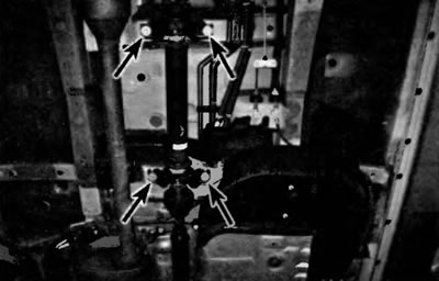
Pic. 4.10. Turn out bolts of fastening of intermediate supports of a cardan shaft
11. Remove the front section of the driveshaft from the transfer case and remove the driveshaft assembly.
12. Lubricate the sealing lips of the transfer box seal with multipurpose grease. Gently guide the intermediate shaft yoke into the transfer case and then screw in the intermediate dispute mounting bolts, but do not tighten them yet.
13. Connect the propeller shaft to the drive gear flange. Don't forget to align the marks you made during removal. Tighten the fasteners to the prescribed torque specified in Specifications at the beginning of this chapter.
14. Fix the intermediate supports. Align them with the marks made during removal and tighten the bolts to the prescribed torque specified in Specifications at the beginning of this chapter.