
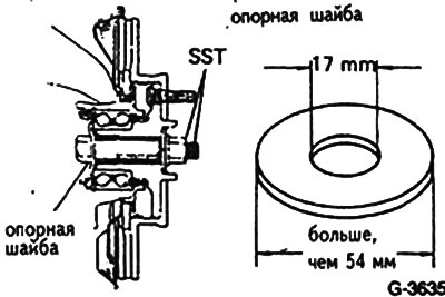
Attention: After removing the drive shafts, the vehicle must not be moved from its place, since in the absence of a longitudinal compression force, the hub bearings may be damaged. If it becomes necessary to move the car, it is necessary to install bolts with thrust washers in place of the removed shafts and compress the bearings with them.
Removing
Loosen the wheel nuts with the car on the ground.
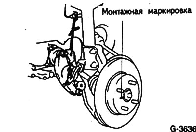
Mark with paint the position of the wheel disk relative to the hub. Thus, the balanced wheel can be installed in its original place.
Raise the front of the car.
Remove wheels.
Straighten and remove the split pin with pliers. Remove crown head from nut.
To give a nut of an axis of a drive, having put the car on a manual brake. The nut loosening force is great! Keep the wrench horizontal when unscrewing to prevent the vehicle from slipping off the supports.
Remove the bottom cover of the engine compartment and drain oil from gearbox.
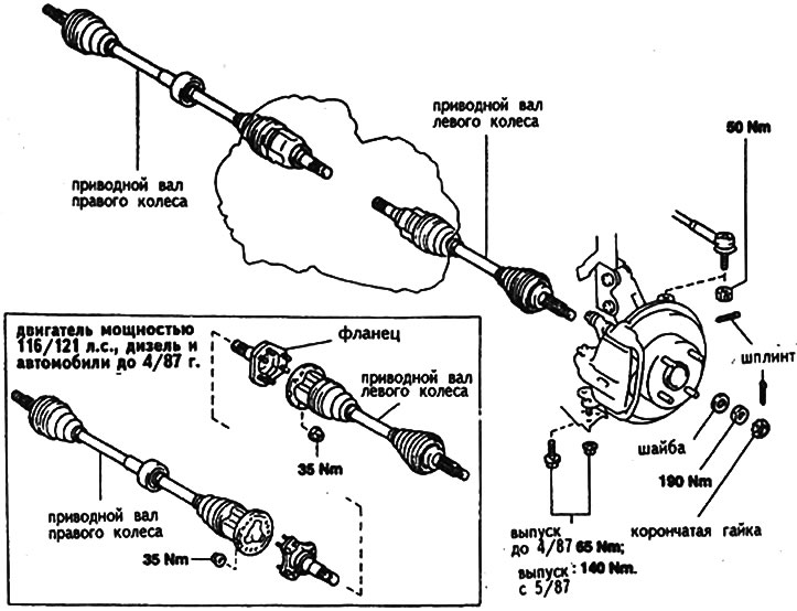
Engine power 116/121 hp, diesel and cars up to 4/87 of release: Loosen 6 drive nuts while holding the brake pedal with the help of an assistant.
Remove the caliper and hang it on a wire to the body.
Remove brake disc. Preliminarily mark the relative position of the brake disc and the wheel hub, in order to be able to install the brake disc in its previous position.
Remove the tip head from the steering arm.
Remove ball joint from control arm, see fig. G3001 earlier.
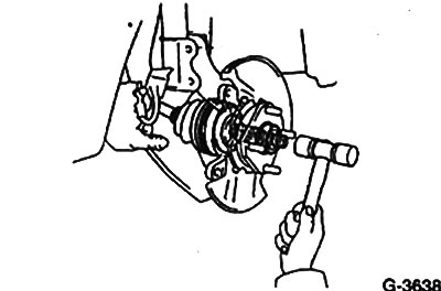
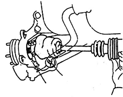
Using a puller or plastic hammer, remove the drive from the wheel hub.
116/121 hp engine, diesel and vehicles up to 4/87: Remove the drive shaft.
Cars of other models:
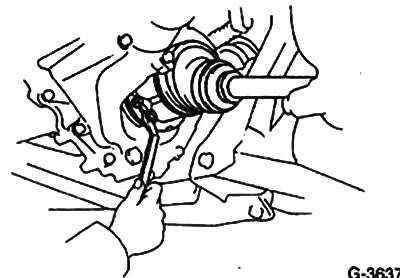
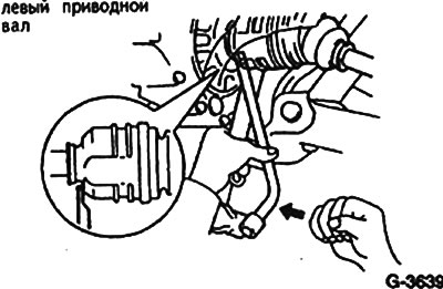
Left drive shaft. Insert a pry bar between the hinge and the gearbox housing. Tilt the mount by pushing out the hinge.
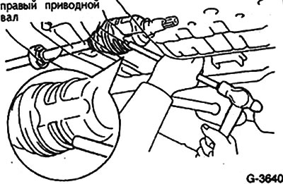
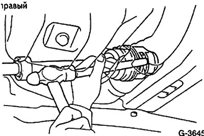
Right drive shaft. Knock out with a brass rod. Do not pull on the drive!
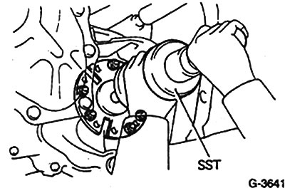
116/121 hp engine, diesel and cars up to 4/87: If it is necessary to remove the drive shaft, first measure the distance between the gearbox housing and the flange with a feeler gauge, pressing the flange towards the gearbox housing. Record the measured value. Screw the impact extractor to the flange and knock out the drive shaft.
Installation
Before assembling the drive, check the sealing collar.
Remove worn cuff. If necessary, you can drill a hole in it and screw a screw into it, then remove the screw along with the cuff. If the seal is damaged or worn, check the bearing for damage and replace it if necessary.
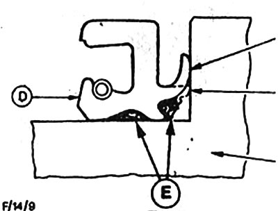
Lubricate the new cuff and lubricate as shown in fig. F / 14/9, and put in place with a piece of pipe.
Clean and lightly coat the connection and threads of the drive shaft.
Insert the drive shaft by hand into the groove of the wheel. Install the washer, screw on the nut and use it to connect the wheel hub to the drive shaft.
116/121 hp engine, diesel and cars up to 4/87 of release:
Carefully use a rubber mallet to reinstall the drive shaft, if it was removed, until the circlip locks into place. The retaining collar must always be installed new. The drive shaft cannot be removed again. Its play of 2-3 mm is allowed. Press the flange against the gearbox housing and measure the distance. It should be the same value as before disassembly.
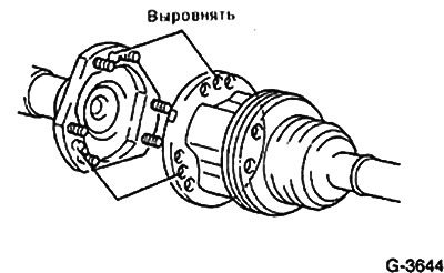
Align the drive on the guide pins and hand-tighten the 6 drive shaft bolts.
Cars of other models:
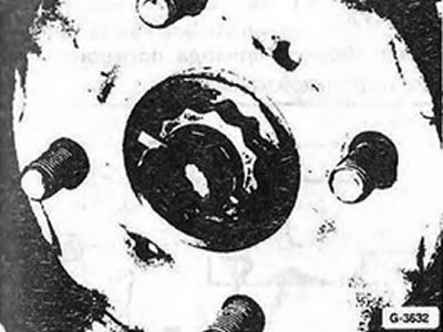
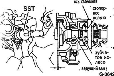
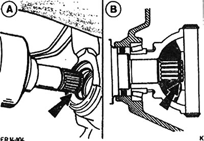
Insert drive shaft with new circlip (arrow in fig. A) into the spline connection of the bevel wheel using a hammer and brass rod. Fix the drive. By moving the shaft along the axis back and forth, check the reliability of fixation. The backlash should be 2-3 mm. The shaft must not be pulled out by hand.
Attach to wishbone ball joint.
Install tie rod end on the shock absorber.
Install the brake disc according to the markings on the wheel hub.
Install brake caliper.
Tighten the wheel drive nut to 190 Nm by applying the foot brake with the help of an assistant. Make sure that the vehicle does not slip off the supports.
Slide the crown head onto the nut. Insert a new cotter pin and separate its ends.
Engine power 116/121 hp, diesel and cars up to 4/87 of release: Fix the drive with 6 bolts with a force of 35 Nm on the drive shaft, pressing the foot brake.
Pour oil into the gearbox.
Install the lower engine compartment cover.
Fasten the wheel with nuts, observing the markings made when removing the wheel.
Lower the front of the vehicle and tighten the nuts crosswise to 105 Nm.
Measure the geometrical parameters of the front suspension.