



Exhaust Gas Recirculation (EGR) System Components
1. The Exhaust Gas Recirculation (EGR) system is used to reduce the nitrogen oxide (NOx) content in the exhaust gases caused by high temperatures in the combustion chamber. The EGR valve recirculates a small amount of exhaust gas into the intake manifold, which helps reduce peak combustion chamber temperatures and thus reduce NOx formation.
2. The EGR system includes a valve, a cooling tube (cooled by the engine cooling system), an electric vacuum regulator and vacuum hoses connecting these components. The EGR valve is installed on the left side of the cylinder head. The vacuum in the EGR system is controlled by a brake system vacuum servo pump, also installed on the left side of the cylinder head.
3. The engine control module (ECM), by supplying power to the electrovacuum regulator, controls the intensity of the recirculated gas flow. If power is supplied to the regulator, the EGR valve opens (because a vacuum is supplied there) and allows the flow of gases into the intake manifold. If there is no power to the regulator, the EGR valve is closed (there is no discharge) and recirculated gases do not pass into the intake manifold.
Examination
Electrovacuum regulator
4. The vacuum regulator can be checked without removing it from the engine. First, disconnect the wiring connector.
5. Measure the resistance between the terminals of the regulator with an ohmmeter and check the measurement results for compliance with the requirements Specifications.
6. Use an ohmmeter to check for continuity between each terminal and the regulator body.
7. Apply volts of direct voltage (power supply) to the terminals of the regulator and create a vacuum in the outlet channel of the regulator, then check that the voltage value is stable.
EGR valve
8. Remove the EGR valve as described in paragraph. 16 of this paragraph.
9. Check for carbon deposits in the regulator channels, which may cause the internal axis to seize; if necessary, clean the channels.
10. Create a vacuum of 200 mmHg in the valve diaphragm chamber and check the lifting of the inner axis to open the upper inlet channel. Blow into the channel and make sure that air flows freely through the lower outlet channel. Keep the vacuum on for a while to ensure that the position of the inner axis on the opening of the channel remains the same.
11. Install the EGR valve as described in paragraph. 17 of this paragraph.
Removal
Electrovacuum regulator
12. Disconnect the vacuum hoses and wiring connector.
13. Loosen the mounting bolts and separate the vacuum regulator from the EGR valve.
EGR valve
14. Remove the vacuum regulator as described earlier.
15. Disconnect the vacuum hose from the diaphragm assembly.
16. Loosen the mounting bolts and nuts and remove the EGR valve from the studs on the cylinder head housing. Remove the gasket and discard it, you will need a new one when installing the valve (see figure 16.16,a,b).
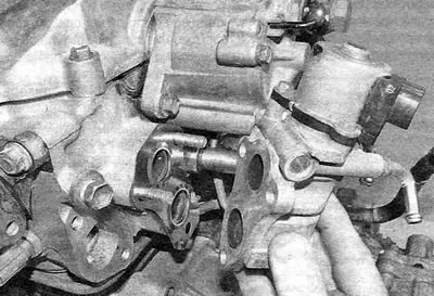
Figure 16.16,a. Remove the EGR valve from the studs...
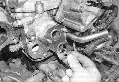
Figure 16.16,b....and remove the gasket.
(The original publication can be found on the website: TOYOTAMAN.ru)
Installation
17. The EGR valve is installed in the reverse order of its removal. Replace the gasket and tighten the mounting bolts and nuts securely.