
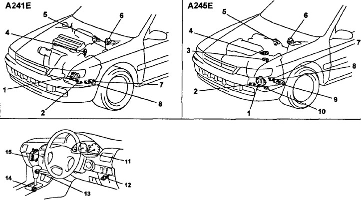
Location of electrical components (models since 1996): 1 - engine start inhibit switch, 2 - torque converter lock-up clutch control solenoid valve, 3 - speed sensor No. 2, 4 - engine coolant temperature sensor, 5 - throttle position sensor, 6 - diagnostic connector, 7 - solenoid valve No. 2, 8 - solenoid valve No. 1, 9 - torque converter lock-up quality control solenoid valve, 10 - automatic transmission fluid temperature sensor, 11 - overdrive off indicator "O/D OFF", 12 - brake light switch, 13 - overdrive switch, 14 - automatic transmission mode selection switch (economical or sporty), 15 - electronic control unit for automatic transmission and engine
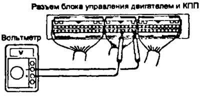
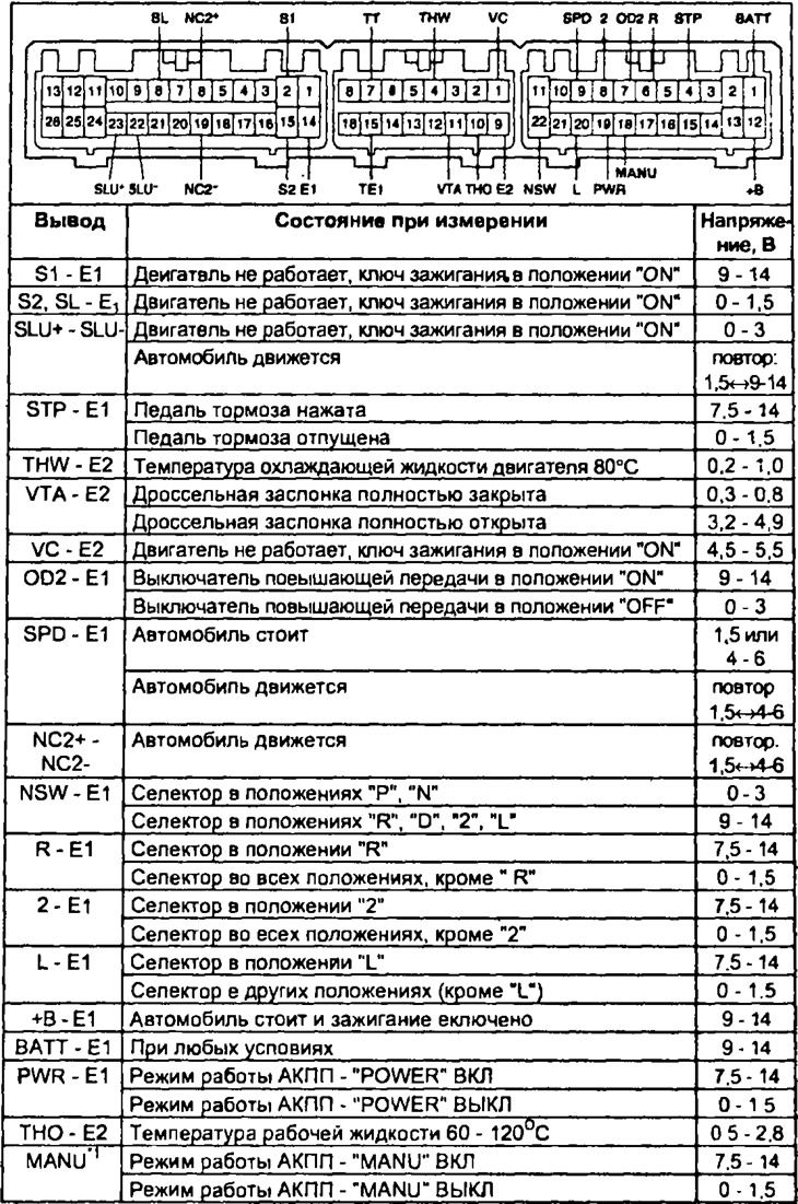
1. Check the voltage at the connector of the automatic transmission and engine control unit.
- V) Remove the center panel.
- b) Turn on the ignition.
- V) Measure the voltage at each pin of the automatic transmission and engine control unit connector (see table 3).
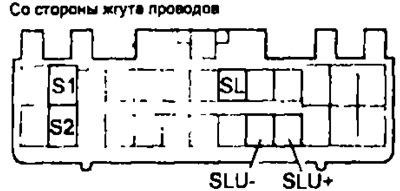
A241E since 1996
Note: For models since 1996:
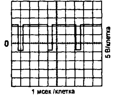
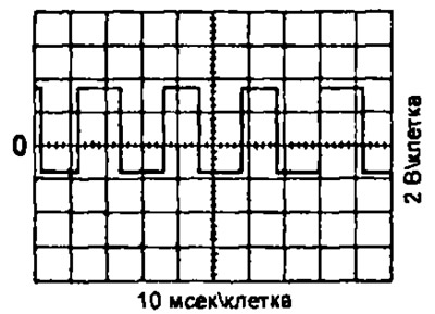
- waveform between pins "SLU-" And "SLU+" when the torque converter lock is off.
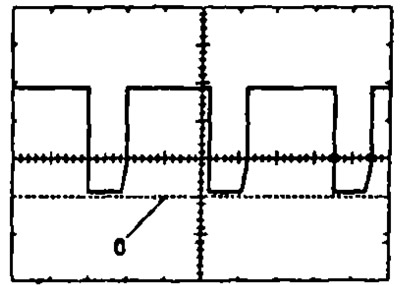
- waveform between pins "SLU-" And "E1" with torque converter lockup engaged.
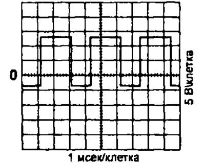
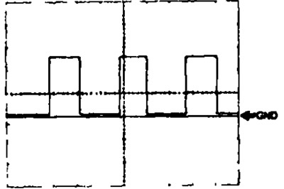
- waveform between pins "SPD" And "E1" when the car is moving at a speed of about 60 km / h.
Note: The higher the vehicle speed, the higher the frequency of the pulses generated by the speed sensor.
- (A245E) waveform between pins "NC2+" And "NC2-" when the car is moving at a speed of about 60 km / h on the range "D".

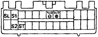
A540N, A241E (since 1996):
- waveform between pins "SPD" And "E1" when the car is moving at a speed of about 20 km / h. Value of division (cells) 5 V and 20 ms.
- waveform between pins "SLD+" And "SLD-", ignition key in position "ON". Value of division (cells) 5 V and 1 ms.
2. Check solenoid valves.
- A) Disconnect the connector from the engine and automatic transmission control unit.
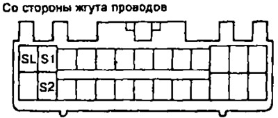
- b) Measure the resistance between terminals S1, S2, ST (only A540H), SL and "earth" or "SLD+" And "SLD-" (A540H only). Resistance 11-15 Ohm.
A240E, A241E
A245E
A540N
- V) (A245E) Measure resistance between leads "SLU+" And "SLU-" and earth. Resistance 5.1-5.5 ohm
- G) Apply battery voltage to each terminal. A click indicates that the solenoid valves are working.
3. (Except A540H) Check the seals of the solenoid valves No. 1, Ne 2 and the blocking valve.
Caution: Foreign material in the solenoid valve may cause it to malfunction.
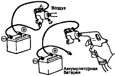
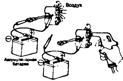
- A) Using compressed air (pressure 490 kPa), check the solenoid valve seals (the valve must not let air through)
- b) Apply battery voltage to the solenoid valve: the valve must allow air to pass through.
(A245E) Check the torque converter lock-up quality control solenoid valve. Connect the positive lead through an 8-10W lamp to the lead "1" solenoid valve connector and negative lead to terminal "2", then check valve movement.
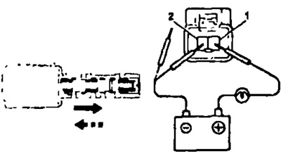
- A) Connect the positive terminal of a regulated voltage power supply to the terminal "1" valve connector and negative terminal to terminal "2".
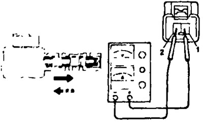
- b) Check valve movement as voltage increases (current should be no more than 1 A). As the voltage increases, the valve should move out slowly.
- V) When the voltage is removed, the valve should slowly return to its original position.
4. A540H. Check the solenoid valve seals.
Caution: Foreign material in the solenoid valve may cause it to malfunction.
- A) Check solenoid valves #1, #2:
- using compressed air, check the solenoid valve seals (the valve must not let air through).
- apply battery voltage to the solenoid valve.
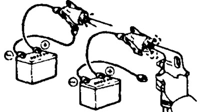
- b) Check the torque converter clutch control solenoid valve.
- supply compressed air to the valve at a pressure of 490 kPa. the valve must not let air through
- drop battery voltage on the solenoid valve, the valve must pass air.
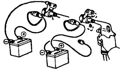
- V) Check the main line pressure solenoid valve.
- supply compressed air to the valve at a pressure of 490 kPa, the valve must not let air through,
- apply battery voltage to the solenoid valve: the valve must pass air.
- G) Check the center differential lock control solenoid valve:
- Connect the positive terminal of the battery through an 8-10 W lamp to the terminal "1" valve connector and negative battery terminal to terminal "2", the valve must move.
- Checking the operation of the valve; Connect the positive terminal of a regulated voltage power supply to the terminal "1" valve connector and negative terminal to terminal "2".
Check the movement of the valve when the voltage is increased (current should be no more than 1 A). As the voltage increases, the valve should retract. When the voltage is removed, the valve should slowly return to its original position.
5. (A245E and A540H) Check speed sensor #2.
Measure the resistance between the sensor connector pins. Rated resistance 560-680 Ohm.
If the measured resistance differs from the nominal, then replace the sensor.
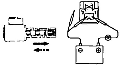
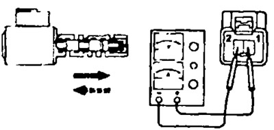
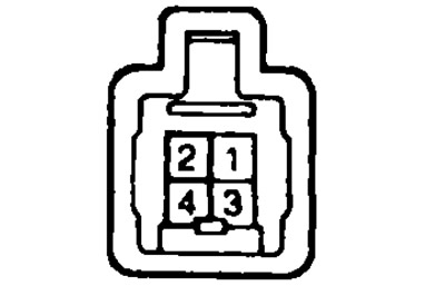
6. Check the start inhibit switch.
Check the continuity between the connector pins indicated in the table.
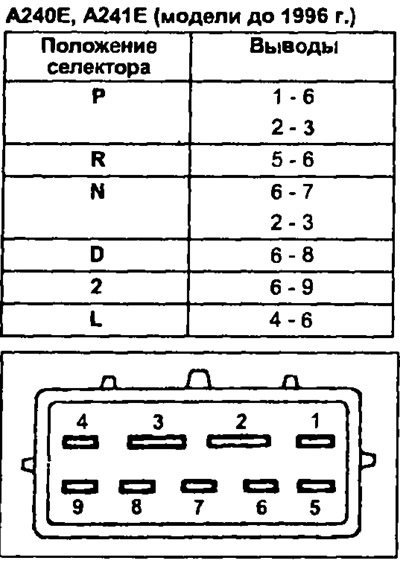 | 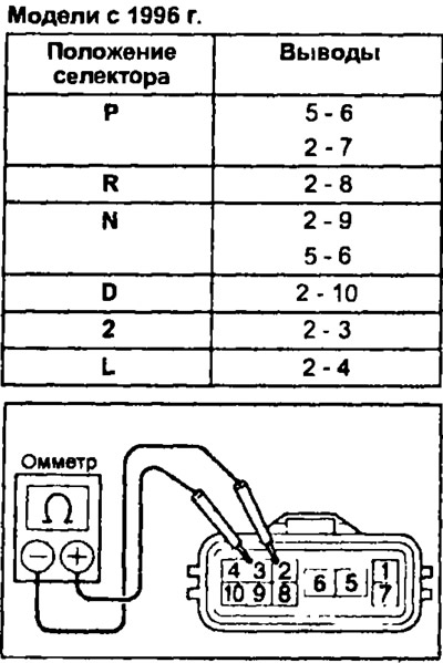 |
If there is no continuity between the indicated terminals, replace the start inhibit switch.
7. Check throttle position sensor.
- V) Measure the resistance between the sensor connector pins shown in the table. If the resistance is not as specified, replace the sensor.
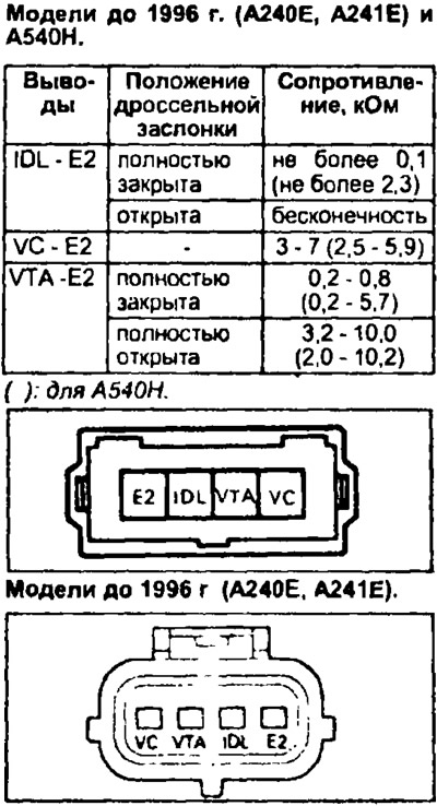 | 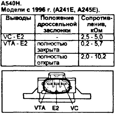 |
8. Models since 1996 Check the automatic transmission mode select switch.
Using an ohmmeter, check the continuity between the terminals of the sensor connector, as indicated in the table.
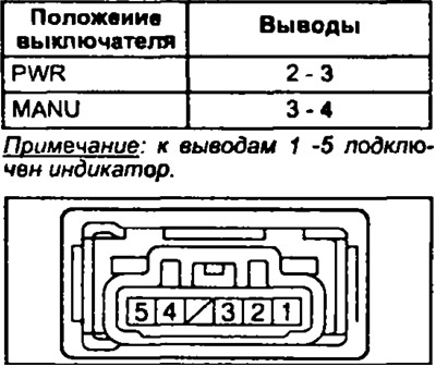
If there is no conductivity between the indicated conclusions. then replace the automatic transmission mode selector switch.
9. Prior to 1996 Models Check speed sensor #2.
- A) Jack up the vehicle so that one of the front wheels can turn freely.
- b) Connect an ohmmeter to the connector pins.
- V) Turn the wheel to make sure the resistance changes from 0 to infinity.
10. Check speed sensor #1. (see chapter "Body electrical equipment").
11. Check the overdrive switch.
- A) Models prior to 1996. Check for continuity between pins 1 and 3.
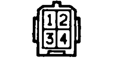
- b) Models since 1996 Check continuity between terminals "2" And "4" overdrive switch connector. When the button is pressed (O/D ON) there should be no conductivity, when the O / D mode is off, there should be conductivity. Otherwise, replace the switch.
12. Check the brake light switch.
Models prior to 1996 Check continuity between terminals "1" And "3".
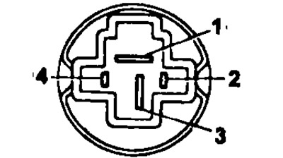
Models since 1996 Check continuity between terminals "1" And "2" brake light switch connector.
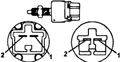
When the pedal is pressed, the conductivity should be, when the pedal is released, there should not be any conductivity. Otherwise, replace the brake light switch.'
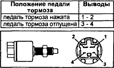
4WD models. Check the continuity between the terminals as indicated in the table.
13. A245E. Check the fluid temperature sensor. Measure the resistance between the sensor connector pins. Resistance:
- at a working fluid temperature of 20°C: 2-3 kOhm
- at a working fluid temperature of 80°C: 0.2-0.4 kOhm
If the resistance is out of specification, replace the sensor.
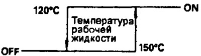
14. A540H. Check the fluid temperature sensor.
Check the continuity between the terminal and the sensor body when the temperature of the working fluid changes, as shown in the figure.
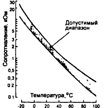
15 Measure the resistance between the terminals of the engine coolant temperature sensor connector. Replace the sensor if the resistance is not as shown.
17. Check the forced downshift switch (kick-down).
- A) Disconnect the kick-down switch connector.
- b) Use an ohmmeter to check for continuity between the terminals "1" And "2" at switch position "ON".
Table 3. Voltage at the contacts of the automatic transmission control unit connector (A241E until 1996)
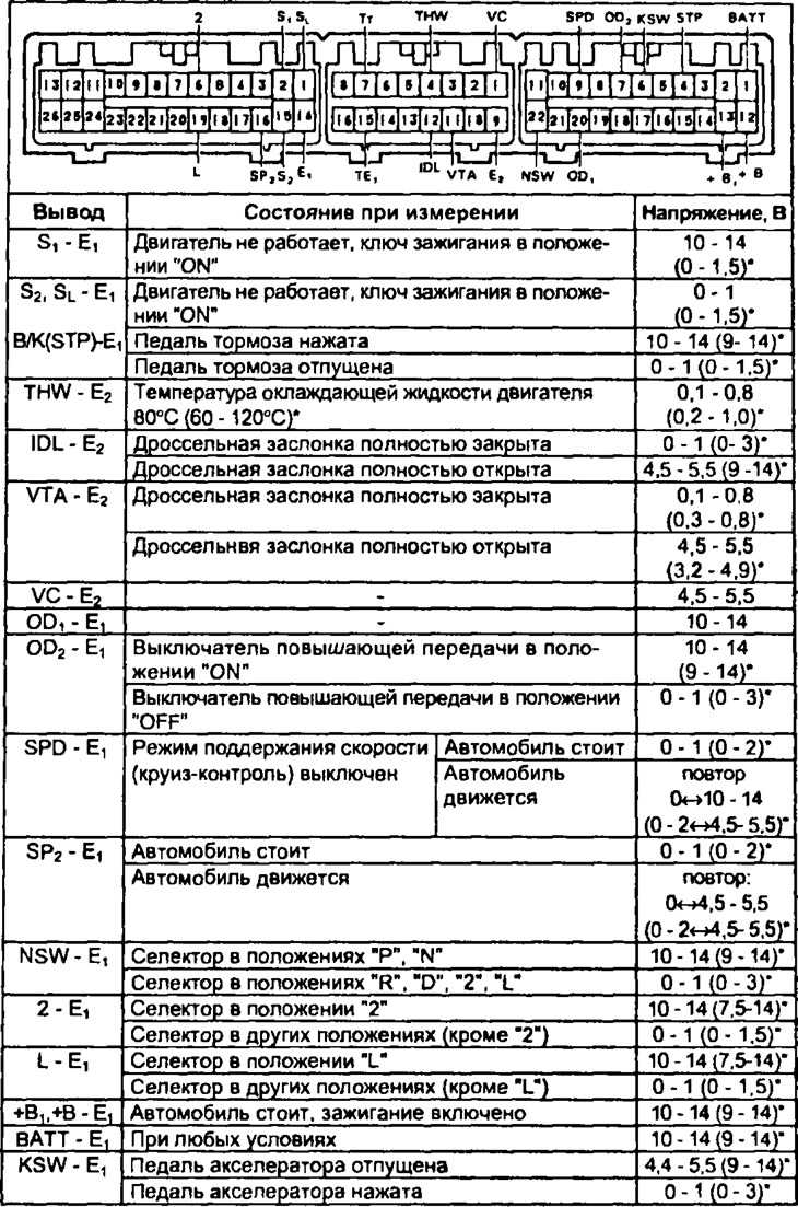
() * - for models with a body "station wagon".
Note, in the connectors of the electronic control unit for automatic transmission and engine models with a body "station wagon", there may be no OD output.
Table 3 (continuation). Voltage at the contacts of the automatic transmission control unit connector (models since 1996: A241E, A54DH)
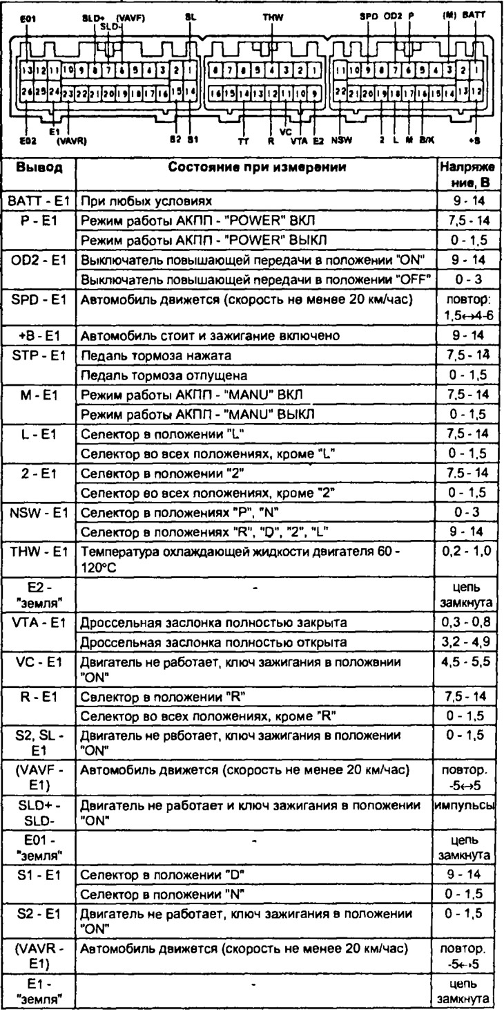
(): for A540H.
Table 3 (continuation). Voltage at the contacts of the automatic transmission control unit connector (A245E)
* - for models from 1996