



Contents: Engine mounts ↓ Replacement ↓
Engine mounts
Examination
1. Engine mounts do not fail often, however, when they do, a damaged or broken mount should be replaced as soon as possible, as this will place increased stress on the transmission components, which will inevitably lead to premature wear or failure.
2. During the inspection, the engine must be suspended in order to relieve the load on the supports.
3. Raise the vehicle and support it on safety stands. Remove the protective covers from the engine (if they exist). Place a jack under the engine oil pan and place a piece of board between the jack head and the oil pan so that the board does not fall under the oil pan drain plug. Carefully lift the engine enough to remove the load from the mounts.
Caution! Do not stand under a vehicle that is supported solely by a jack.
4. Check the rubber support pads for cracks, separation from metal parts, subsidence or decomposition of the rubber by gently rocking them with a powerful screwdriver or mounting spatula, check for wear and gaps between the support parts.
5. Where this is not possible, have an assistant rock the engine back and forth and side to side while watching the mounts. If there is wear, play will be obvious. If no defects are found, check the tightening of the support fasteners with a torque wrench where possible. Replace damaged parts as described below.
6. Apply a protective coating to the rubber pads of the supports to slow down the decomposition of the rubber.
Replacement
7. Disconnect the negative battery cable, lift the vehicle and place it on safety stands (if it hasn't already been done). Raise the engine as described in paragraph. 3.
Right support
8. Working under the vehicle, unscrew the nut securing the right engine mount bracket (see Figure 16.8).
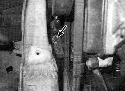
Figure 16.8. Get under the vehicle and unscrew the nut securing the right engine mount bracket.
9. Turn over from the top (in the engine compartment) nuts and bolts securing the right engine mount (see Figure 16.9).
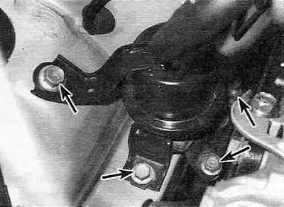
Figure 16.3. Unscrew the reconciliation (in the engine compartment) bolts/nuts securing the right engine mount (shown by arrows).
If the car is equipped with ABS (anti-lock braking system), then to access the right support you must first remove the ABS hydraulic modulator and the bracket that mounts it to the engine (see chapter 9).
10. Remove the right support from the vehicle.
11. Installation of the new support and all other actions are performed in the reverse order of removal. Before installation, lubricate the threaded parts of the bolts/nuts with a locking sealant and tighten them to the specified torque (see Specifications).
Warning. After installing the ABS hydraulic modulator in place (if it is provided) don't forget to bleed the brake system (see chapter 9).
Front and rear transmission mounts
12. Loosen the bolts securing the front/rear transmission mounts to the front suspension crossmember (see Figure 16.12).
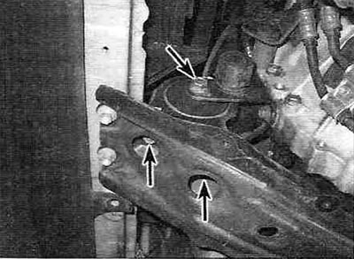
Figure 16.12. Mounting bolts (shown by arrows) transmission mounts - the front mount is shown, the rear one looks the same.
13. Loosen the through bolt securing the front (rear) support to the transmission bracket and remove the support.
14. Installation of the front (rear) support is carried out in reverse order. Before installation, lubricate the threaded parts of the bolts/nuts with a locking sealant and tighten them to the specified torque (see Specifications).
Left transmission support
15. Remove the air filter housing (see chapter 4A).
16. Loosen the bolts and nuts securing the spore to the transmission (see figure 16.16).
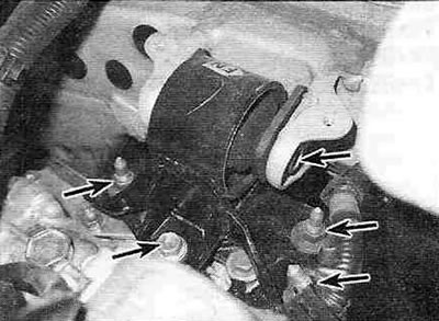
Figure 16.16. Left transmission support mounting bolts/nuts (shown by arrows).
17. Unscrew the through bolt securing the support to the frame and remove the support from the vehicle.
18. Installation of the new support is carried out in reverse order. Before installation, lubricate the threaded parts of the bolts/nuts with a locking sealant and tighten them to the specified torque (see Specifications).