
Numbering of conclusions of the switch of the electric drive of mirrors
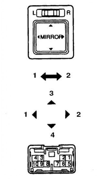
1. Left side; 2. Right side; 3. Up; 4. Down
Numbering of conclusions of the switch of the electric motor of mirrors
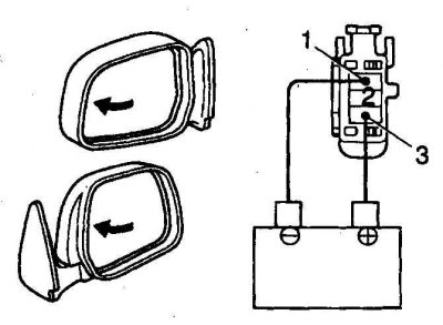
1. The mirror drive is carried out from 2 vertical and horizontal displacement electric motors.
2. Turn on the ignition (do not start the engine) and lower the side windows. With the selector mounted in the switch, turn on the desired mirror and check the operation of the drive of the right and left mirrors, shifting them to the right and left, up and down. Listen to the operation of the electric motors.
3. If the operation of the electric motors is tapped, and the mirror does not move, then the drive mechanism inside the mirror is faulty. Remove the mirror and disassemble.
4. If the operation of the electric motors is not heard and the mirrors do not move, then check the fuse.
5. If the fuse is good, then remove the switch without disconnecting the wires. Turn on the ignition and check the voltage at the switch. If there is no voltage, then check the wires from the fuse to the switch. If not, check the switch by doing the following: (see fig. Numbering of conclusions of the switch of the electric drive of mirrors).
Left mirror
6. In the UP position of the switch, the circuit must be between pins 6 and 10, and between pins 1 and 9.
7. In the DOWN position of the switch, the circuit must be between pins 1 and 10, and between pins 6 and 9.
8. In the LEFT position of the switch, the circuit must be between pins 5 and 9, and between pins 6 and 10.
9. In the RIGHT position of the switch, the circuit must be between pins 5 and 10, and between pins 6 and 9.
Right mirror
10. In the UP position of the switch, the circuit must be between pins 6 and 10, and between pins 1 and 9.
11. In the DOWN position of the switch, the circuit must be between pins 1 and 10, and between pins 6 and 9.
12. In the LEFT position of the switch, the circuit must be between pins 5 and 9, and between pins 6 and 10.
13. In the RIGHT position of the switch, the circuit must be between pins 5 and 10, and between pins 6 and 9.
14. If results of checks negative replace the switch.
15. Connect the switch. Locate the wire from the switch to ground. Without disconnecting the switch, short this wire to ground with a jumper. If the mirror is working properly with the jumper, then repair "regular" ground connection.
16. If the mirror does not work, then disassemble the mirror and check for voltage on the wires. Turn on the ignition and move the switch to all positions, checking the voltage. There should be voltage on one of the wires from the switch in each of its positions (except for the Off position).
17. If there is no voltage, then check the circuit from the mirror to the switch.
18. If there is voltage, then check the motor by doing the following: (see fig. Numbering of conclusions of the switch of the electric motor of mirrors).
19. Check the movement of the mirror to the left, for which connect with a jumper (+) - battery terminal with terminal 3, and (-) - output - with output 1.
20. Reverse the polarity and make sure the mirror moves to the right
21. Check the movement of the mirror up, for which connect with a jumper (+) - battery terminal with terminal 2, and (-) - output - with output 1.
22. Reverse the polarity and make sure the mirror moves down.
23. If the test results are negative, then replace the mirror assembly.