
Caution: When using the vise, do not damage the pump housing.
1. Measure the clearance between the pump shaft and the casing sleeve.
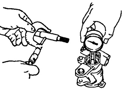
Oil clearance:
- standard: 0.01-0.03mm
- maximum: 0.07mm
2. Checking the rotor and blades.
- A) Using a micrometer, measure the height, thickness and length of the blades.
- Minimum height 8.0 mm
- Minimum thickness 1,770 mm
- Minimum length 14.97 mm
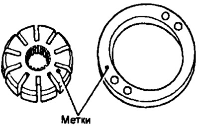
- b) Using a feeler gauge, measure the clearances between the rotor and blades. The maximum clearance is 0.03 mm. If the clearance is greater than the maximum, replace the vanes and/or rotor with new ones with the same markings as on the stator ring.
Labeled 1, 2, 3, 4 or no label.
Note: Five blade lengths are available with the following rotor and stator ring marks:
| Rotor and stator ring mark | Blade length, mm |
| No label | 14,996 -14,998 |
| 1 | 14,994-14,996 |
| 2 | 14,992-14,994 |
| 3 | 14,990-14,992 |
| 4 | 14,988-14,990 |
3. Checking the flow regulator.
- A) Apply hydraulic fluid to the flow regulator and check that it slides smoothly into the orifice under its own weight.
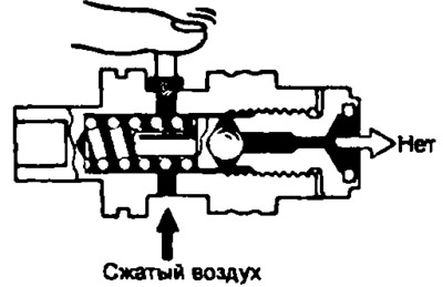
- b) Check flow regulator for leaks. Close one of the side holes and supply compressed air at a pressure of 392-490 kPa to the opposite hole, the air should not come out of the end hole of the flow regulator.
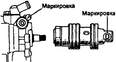
If necessary, replace the flow regulator with a new one in accordance with the markings on the housing. Marking: A, B, C, D, E or F.
4. Using a ruler, measure the free length of the spring. Spring length 36-38 mm.
5. If necessary, replace the gland.
- A) Using a screwdriver, remove the seal.
- 6) Using a suitable mandrel, press in a new oil seal.