
Generator parts (typical variant)
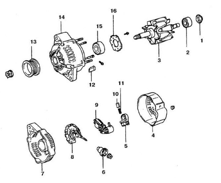
1, 16. Bearing cap; 2, 15. Bearing; 3. Rotor; 4. Back cover; 5. Brush holder; 6. Insulating sleeve; 7. Rear bearing housing; 8. Rectifier contact plate; 9. Voltage regulator; 10. Brush; 11. Spring; 12. Buffer; 13. Pulley; 14. Front cover
Check and replacement
1. Remove the generator.
2. Loosen the rear cover nuts.
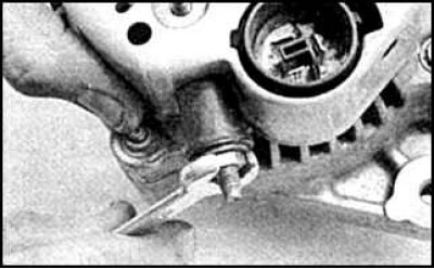
3. Loosen the alternator output nut.
4. Remove the outlet grommet and rear cover.
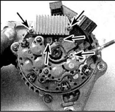
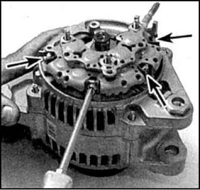
5. Unscrew the screws of the voltage regulator and brush holder (indicated by arrows).
6. Remove the brush holder.
7. Remove the voltage regulator.
8. Further disassembly is only necessary to replace the brushes.
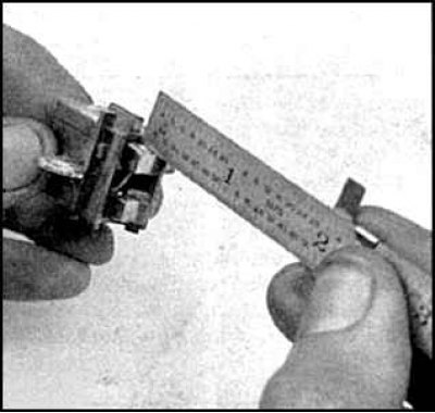
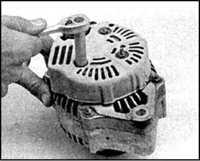
9. Measure the length of the protruding part of the brushes.
10. If the brush length is less than the maximum allowable, replace the brush holder assembly with brushes. On some cars, only the brushes can be replaced by soldering them.
11. Make sure the brushes move freely in the brush holder.
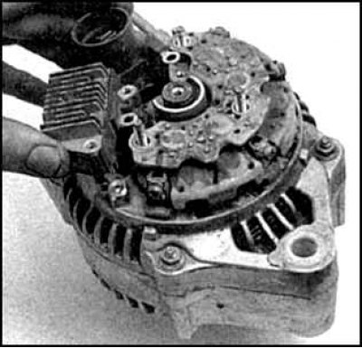
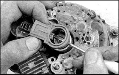
12. Remove the rectifier (arrows indicate mounting screws).
13. Remove 4 buffers and mud deflector.
14. Mark the position of the front and rear covers.
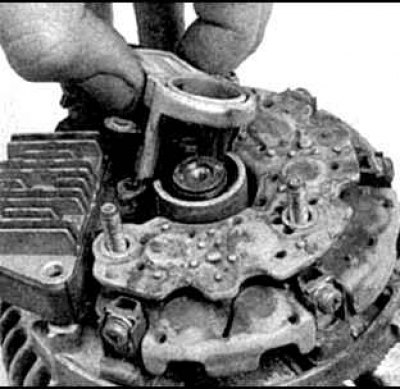
15. Loosen the nut and remove the pulley.
16. Turn away 4 nuts and disconnect the case of the back bearing.
17. Remove the thrust washer and remove the rotor.
Checking and assembly
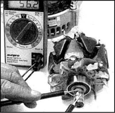
1. Check the resistance between the slip rings, which should be 2-4 ohms.
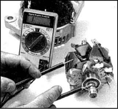
2. Check the circuit between the rotor shaft and slip rings. The ohmmeter should show infinite resistance.
3. The rotor is defective if the results of both checks are unsatisfactory, or in case of excessive wear of the rings.
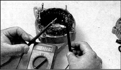
4. Check the resistance between the stator winding leads.
5. If the resistance is high, or the ohmmeter shows an open, then the stator is faulty.
6. Check the short circuit of the stator windings on the case (core).
7. Attach the positive probe of the ohmmeter to the terminal, and the negative probe to ground. The device should show a closed circuit (1 - positive probe, 2 - negative probe).
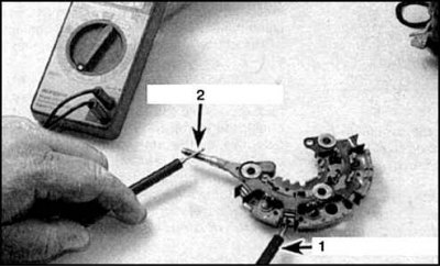
8. When changing the polarity of the ohmmeter connection, a break should be observed (1 - positive probe, 2 - negative probe).
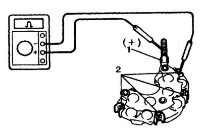
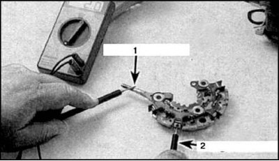
9. Check Rectifier Positive Diodes (1 - positive terminal, 2 - diode terminals).
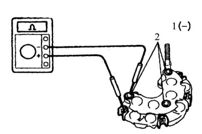
10. Check Rectifier Negative Diodes (1 - negative terminal, 2 - diode terminals).
11. Assembly is carried out in the reverse order.
12. Press the brushes when installing the brush holder.