Rotor check
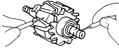
1. Check for an open in the field winding.
Use an ohmmeter to measure the resistance between the slip rings.
- Rated resistance (cold) - 2.7 - 3.1 ohm
If the resistance tends to infinity, i.e. circuit is open, replace the rotor.
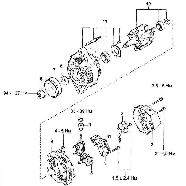
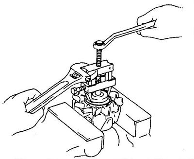
Disassembly and assembly of the generator.
1 - output insulator,
2 - back cover,
3 - brush holder,
4 - voltage regulator,
5 - rectifier block,
6 - nut,
7 - pulley,
8 - spacer,
9 - body,
10 - rotor,
11 - drive side cover.
2. Check for a short circuit in the field winding to ground.
Using an ohmmeter, measure the resistance between the rotor pole and the slip ring.
If resistance is 0 (circuit is closed), replace the rotor.
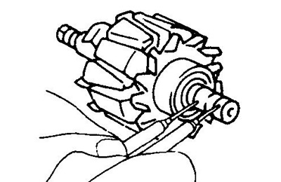
3. Check slip rings.
A) Check the working surfaces of the slip rings. They should not have scuffs or chips.
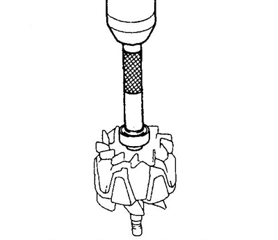
b) Using a caliper, measure the diameter of the slip rings.
- Nominal diameter - 14.2 -14.4 mm
- Minimum allowable - 12.8 mm
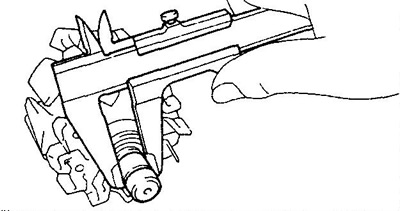
If the slip ring diameter is less than the minimum, replace the rotor.
Stator check
1. Check for an open in the stator winding.
Using an ohmmeter, measure the resistance between the terminals of the stator winding coils.
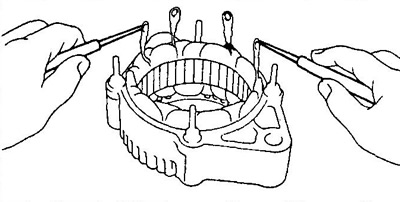
If the resistance tends to infinity, i.e. open circuit, replace stator.
2. Check if the stator winding is shorted to ground.
Using an ohmmeter, measure the resistance between the stator housing and the stator coil leads.
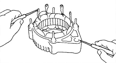
If the resistance is "0", i.e. circuit is shorted, replace the stator.
Check voltage regulator.
Using an ohmmeter, measure the resistance between the terminals of the voltage regulator.
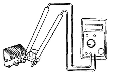
If the resistance tends to infinity, i.e. open circuit, replace voltage regulator.
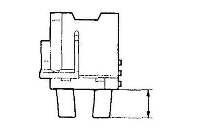
Checking the brushes
1. Measure the length of the protruding part of the brushes.
- Nominal length - 10.5 mm
- Minimum allowable - 1.5 mm
Rectifier unit check
1. Checking the positive valve.
A) Connect the negative probe of an ohmmeter to the positive terminal of the rectifier unit, and connect the positive probe in series to each of the other three terminals.
Check for conductivity (closed circuit) in all three dimensions.
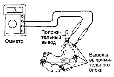
b) Reverse the polarity of the tester probes and repeat the procedure of paragraph (V). Make sure the circuit is open in all three dimensions (resistance tends to infinity).
If the conditions are not met, replace the rectifier unit.
2. Checking the negative valve.
A) Connect the positive probe of the ohmmeter to the negative terminal of the rectifier unit, and connect the negative probe in series to each of the other three terminals. Check for conductivity (closed circuit) in all three dimensions.
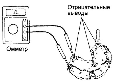
b) Reverse the polarity of the tester probes and repeat the procedure of paragraph (A). Make sure the circuit is open in all three dimensions (resistance tends to infinity).
If conditions are not met, replace the rectifier unit.
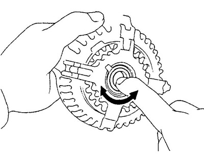
Bearing check
1. Checking the front bearing. Make sure the rear bearing runs smoothly without binding.
2. Replace the bearing if necessary.
A) Loosen the 4 screws and remove the bearing holder.
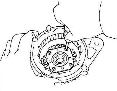
b) Using a press and an appropriately sized socket, press out the front bearing.
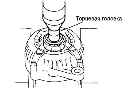
V) Using a special punch and a press, press the new front bearing into the drive side alternator cover.
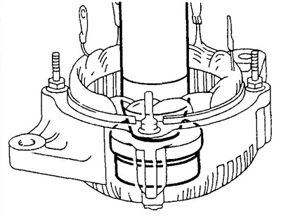
G) Install the bearing holder and tighten the 4 screws securing it.
- Tightening torque - 2.6 Nm
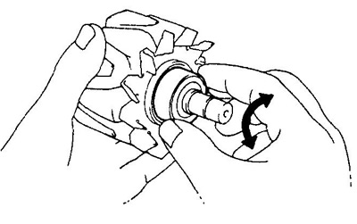
3. Checking the rear bearing.
Make sure the rear bearing runs smoothly without binding.
4. If necessary, replace the rear bearing.
A) Using a puller, remove the rear bearing and bearing cap.
b) Using a press, install the new rear bearing onto the rotor shaft.
V) Install the bearing cover.