
Disassembly
Typical design of an automotive alternator
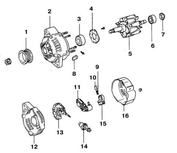
1 - Pulley; 2 - Cover on the drive side; 3 - Front bearing; 4 - Holder; 5 - Rotor; 6 - Rear bearing; 7 - Bearing cover; 8 - Rubber insulating insert; 9 - Spring; 10 - Brush; 11 - Voltage regulator; 12 - Cover from the side of slip rings; 13 - Rectifier assembly holder; 14 - Terminal insulator; 15 - Brush holder with cover; 16 - Back cover
1. Remove the generator from the engine (see Section Removal and installation of the generator) and place it on a clean workbench.
2. Loosen the rear cover nuts, loosen the B terminal nut, remove the washer and grommet from the terminal, then remove the cover (refer to illustration above).
3. Remove the screws securing the voltage regulator and brush holder.
4. Remove the brush holder and voltage regulator from the back of the frame. If dismantling was done to replace the regulator, proceed to paragraph 8 procedure, install a new unit, assemble the generator and install it on the engine (see Section Checking the state of the charge system). The following paragraphs describe the procedure for replacing brushes.
5. Measure the amount of protrusion of each of the brushes, if the measurement results are outside the lower limit of the allowable range (see Specifications), replace the brushes complete with the holder.
Note. On some models, a soldering iron may be required to replace the brushes.
6. Check up smoothness of the course of brushes in guides of the holder.
7. Remove the rectifier assembly. Remove the four rubber insulating inserts and the sealing plate.
8. Using a marker or scriber, mark the mutual mounting position of the front and rear casings of the generator.
9. Give a fixing nut and remove a driving pulley from a rotor shaft of the generator.
10. Give four fixing nuts divided generator assembly into two parts.
11. Remove the thrust washer and remove the rotor from the front of the assembly.
Examination
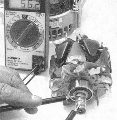
1. Measure the resistance between two sliding rings (refer to accompanying illustration), the nominal value is 2-4 ohms. Check for continuity between each of the slip rings and the rotor assembly. If the test fails, or if the slip rings are excessively worn, replace the rotor.
2. Check for an open in the generator stator windings, continuity must be present between each pair of end terminals of the assembly. If the ohmmeter shows an infinite reading on any of the measurements, replace the stator. Check windings for signs of breakdown to ground (the presence of conductivity between the terminal and the frame. A defective stator must be replaced.
3. Check the condition of the positive and negative sections of the rectifier.
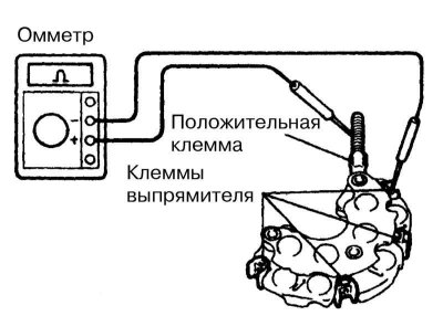
- a. You should start by checking the positive section - the assembly should have conductivity in only one of the directions, a change in polarity should lead to a change in the situation to the opposite (refer to accompanying illustration). It is necessary to check each of the terminals of the assembly in turn;
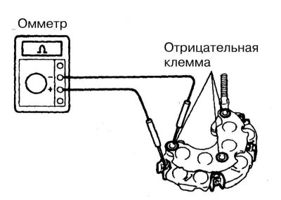
- b. Next, proceed to check the negative section - proceed in a similar manner (refer to accompanying illustration).
Assembly
1. Installation of components is carried out in the reverse order of their dismantling. Pay attention to the order of the procedures.
2. When landing the brush holder on the generator shaft, use a small screwdriver to press each of the carbon brushes in turn.
3. Screw in the screws securing the brush holder and voltage regulator.
4. Track reliability of a tightening of three nuts of fastening of a back cover.
5. Assemble the terminal assembly and secure its components with your nut.
6. Install the generator on the engine (see Section Removal and installation of the generator).