
Note. Since emission control components such as the catalytic converter are covered under warranty, contact your dealer's service department before replacing the converter yourself.
Note. The front catalytic converter is integrated into the exhaust manifold. For a description of the procedure for replacing the exhaust manifold, refer to the chapter 2A or 2B.
General description
1. A catalytic converter is an emission control device installed in the exhaust system. It reduces the level of pollutants in the exhaust gas stream. There are two types of catalytic converters. Oxidation Catalyst Reduces Hydrocarbon Levels (NS) and carbon monoxide (SO) by adding oxygen to the exhaust gas stream to get no water vapor escaping (H20) and carbon dioxide (carbon dioxide) (CD2). Reducing catalytic converter reduces nitrogen oxide levels (NO2) by removing oxygen from the exhaust gases to produce nitrogen (N) and oxygen. Both types of converters are combined into one three-way catalytic converter that reduces levels of all three pollutants.
2. The amount of oxygen entering a catalytic converter is the determining parameter for its operation, because without oxygen it cannot convert harmful pollutants into harmless components. The catalytic converter is most effective at oxygen intake and storage when it neutralizes the exhaust gases generated after the combustion of the air-fuel mixture with an ideal (stoichiometric) ratio «air is fuel», i.e. 14.7:1. If the ratio «air is fuel» over an extended period of time less (poorer) stoichiometric ratio, the catalytic converter will store even more oxygen. But if the ratio «air is fuel» over any period of time «richer» stoichiometric ratio, the oxygen content in the converter may be completely depleted. If this condition occurs, the catalytic converter will not perform any neutralization at all!
3. Since the ability of a catalytic converter to store oxygen is an important factor for its efficient operation, this parameter can also be considered as an indicator of the possible inability of the converter to do its job. The PCM monitors the oxygen content at the inlet and outlet of the catalytic converter by comparing the voltage signals from the front and rear oxygen sensors. When the catalytic converter is working properly, very little oxygen is registered at the outlet of the catalytic converter, because the latter captures, stores and releases the oxygen necessary to neutralize HC, CO and NO, and more harmless components. If the catalytic converter is not doing its job, the rear oxygen sensor tells the PCM that the oxygen content in the neutralized exhaust gases is rising. When the amount of oxygen leaving the converter reaches a prescribed threshold, the PCM generates a DTC (DTC) and turns on the malfunction indicator lamp (MIL), also known as «control lamp Check engine (check engine)».
Examination
4. Catalytic converter testing equipment is very complicated and expensive. If you suspect that the converter on your vehicle is malfunctioning, contact your dealer or other authorized service station for diagnosis and repair.
5. Check the catalytic converter for leaks, signs of corrosion, dents, or other damage each time the vehicle is lifted to service the underbody. Check the flange welds/bolts that connect the front and rear ends of the converter to the exhaust system. If damage is found, the converter should be replaced.
6. Although catalytic converters do not fail too often, they can become blocked. The easiest way to check for catalytic converter capacity reduction is to use a vacuum gauge to diagnose the effect of a blockage in the exhaust system on intake vacuum.
- A) Connect a vacuum gauge to the intake manifold vacuum control port (see chapter 2B).
- b) Warm up the engine to operating temperature, put the transmission into park (Automatic transmission) or neutral position (Manual Transmission) and apply the parking brake.
- V) Take an idle vacuum reading and record it.
- G) Quickly open the throttle to almost fully open and release it to return to the closed position. Take and record the vacuum reading.
- d) Run the test three more times, recording the reading after each test.
- e) If, after the fourth test, the reading is lower than the value registered at idle by more than 25 mm Hg. Art., the exhaust system may be clogged (the catalytic converter may be clogged or the exhaust pipe or muffler may be clogged/deformed).
Replacement
Attention! Do not service the catalytic converter until it has completely cooled down.
Front catalytic converters
Models with four-cylinder engines
Note. On models 2001-2003. with a four-cylinder engine, two front catalytic converters are installed. On Toyota vehicles, they are referred to using the abbreviation WU TWC, which literally translates to heated three-way catalytic converter. They are an integral part of the exhaust manifold. 2004 and later models with a four-cylinder engine have one front catalytic converter (also type WU-TWC), and it is also an integral part of the exhaust manifold.
7. Refer to paragraph «Exhaust manifold assembly with catalytic converter» in chapter 2A.
Models 1999-2003 with V6 engine
Note. On models 1999-2003. with V6 engine heated three-way catalytic converters (WU-TWC) located directly below the exhaust manifolds to which they are bolted.
8. Raise the front of the car and place secure supports under it.
9. To remove the three-way catalytic converter of the front row of cylinders, unscrew the two nuts that are used to fasten the upper end of this converter to the exhaust manifold, and the two nuts that are used to fasten the lower end of the converter to the connecting pipe (pic. 18.9, a, b).
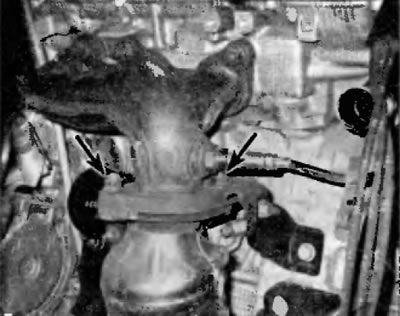
Pic. 18.9, a. To disconnect the upper end of the front three-way catalytic converter from the front exhaust manifold on a V8 engine, remove the two nuts
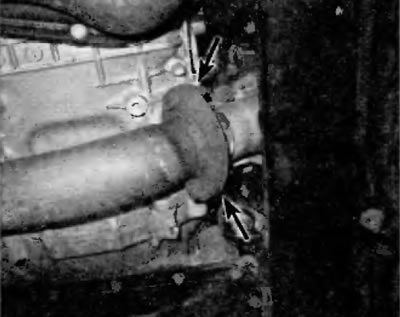
Pic. 18.9, b. To disconnect the lower end of the front three-way catalytic converter from the connecting pipe on the V6 engine, unscrew the two nuts and remove the bolts
10. To remove the three-way catalytic converter of the rear row of cylinders, unscrew the nuts and remove the bolts that are used to connect the converter to the rear exhaust manifold, connecting pipe and rear catalytic converter (pic. 18.10).
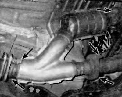
Pic. 18.18. To disconnect the three-way catalytic converter from the rear exhaust manifold, connecting pipe and rear catalytic converter, loosen the nuts and remove the bolts
11. Installation is carried out in the reverse order of removal.
2004 and later models with V6 engine
Note. On 2004 and later models with V6 engines, the exhaust manifold and three-way catalytic converter are welded together and therefore cannot be serviced separately.
12. Refer to paragraph «Exhaust manifolds with catalytic converters» in chapter 2B.
Rear catalytic converter
Note. The rear catalytic converter, which on Toyota and Lexus vehicles is a three-way catalytic converter (TWC), located under the bottom of the vehicle. It is located between the flange at the rear end of the front exhaust pipe and the muffler, to which it is connected by a short pipe. The three-way catalytic converter, short pipe and muffler are welded together into a single unit.
13. Raise the front of the car and place secure supports under it.
14. See pictures 16.1, b, c in chapter 4.