
2. Disconnect the connector from the actuator.
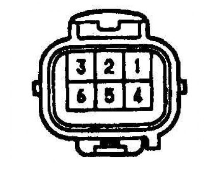
3. Check the resistance between terminals 2 and 3 of the connector.
4. Check the resistance between terminals 2, 3 and ground.
5. If the resistances are out of range. then replace the actuator.
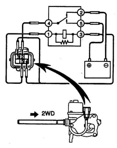 | 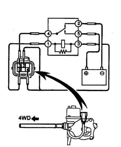 |
6. Check the operation of the actuator by feeding the appropriate terminals from the battery through the heater relay according to the diagram. When voltage is applied through the relay to pin 5, the actuator plug should retract (diagram on the left) (front axle off), and when voltage is applied, pin 3 of the plug should extend (front axle engaged) (diagram on the right).
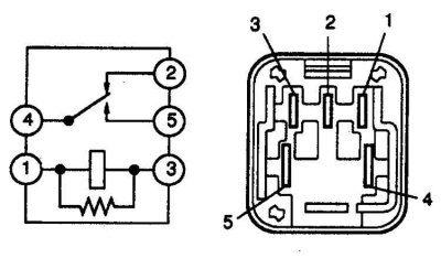
7. To test the actuator, the main heater relay, or similar, is used.
8. If the actuator does not work as described above, then replace the actuator.
Actuator limit switch
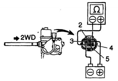
9. Connect (+) batteries with output 2, and (-) battery terminal 3. () connect the output of the ohmmeter to terminal 5, and (-) the output of the ohmmeter is with terminal 4. The ohmmeter should show a circuit between terminals 4 and 5.
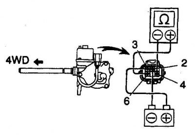
10. Connect (+) batteries with terminal 3, and (-) battery terminal 2. () connect the output of the ohmmeter to terminal 6, and (-) the output of the ohmmeter is with terminal 4. The ohmmeter should show a circuit between terminals 4 and 6.
11. If the switch does not work as described above, then replace the actuator.