



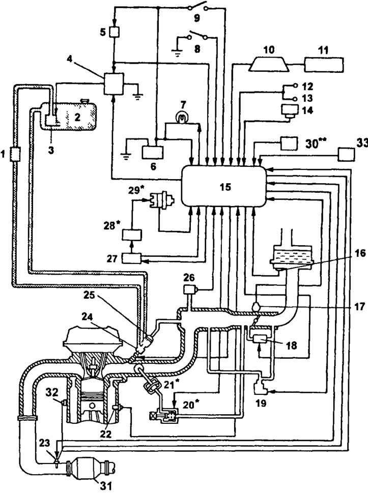
Fuel injection system diagram (4A-FE): 1 - fuel filter; 2 - Fuel Tank; 3 - fuel pump; 4 - fuel pump switch relay; 5 - main relay of the fuel injection system; 6 - battery; 7 - "CHECK" control lamp; 8 - diagnostic connector; 9 - ignition switch; 10 - instrument cluster; 11 - speed sensor No.1; 12 - rear light relay; 13 - Rear window defroster switch; 14 - air conditioner amplifier (for models with air conditioning); 15 - electronic control unit; 16 - intake air temperature sensor; 17 - throttle position sensor; 18 - idle speed control valve; 19 - idle speed increase control solenoid valve (for models with air conditioning); 20 - Electro-pneumatic valve of the intake manifold geometry change system; 21 - actuator of the intake manifold geometry change system; 22 - coolant temperature sensor; 23 - oxygen sensor; 24 - nozzle; 25 - fuel pressure regulator; 26 - absolute pressure sensor in the intake manifold; 27 - Switch; 28 - ignition coil; 29 - distributor; 30 - variable resistor (serial version); 31 - catalytic converter; 32 - knock sensor (serial version) 33 - Start inhibit switch (models with automatic transmission).
* - models with Learn Burn system.
** - modifications.
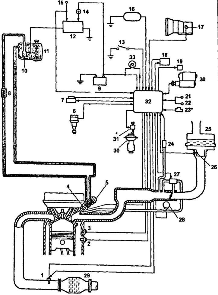
Fuel injection diagram (3S-FE; 4S-FE): 1 - oxygen sensor; 2 - coolant temperature sensor; 3 - knock sensor; 4 - nozzle; 5 - fuel pressure regulator; 6 - distributor; 7 - Switch; 8 - fuel filter; 9 - battery; 10 - fuel pump; 11 - fuel tank; 12 - Fuel pump relay switch; 13 - diagnostic connector; 14 - main relay of the fuel injection system; 15 - ignition switch; 16 - speed sensor; 17 - start inhibit switch (models with automatic transmission); 18 - air conditioner amplifier; 19 - valve of the system of increasing the speed of rotation when the air conditioner is turned on; 20 - starter; 21 - Tail light relay; 22 - Rear window heater relay; 23 - variable resistor; 24 - absolute pressure sensor in the intake manifold; 25 - air filter; 26 - intake air temperature sensor; 27 - idle speed control valve; 28 - throttle position sensor; 29 - catalytic converter; 30 - exhaust gas recirculation valve; 31-electropneumatic valve of the exhaust gas recirculation system; 32 - electronic fuel injection control unit.
* - modifications.
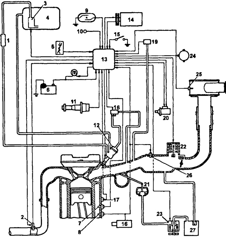
Fuel injection system (3S-GE - variable geometry intake manifold system): 1 - fuel filter; 2 - oxygen sensor; 3 - fuel pump; 4 - fuel tank; 5 - variable resistor; 6 - battery; 7 - coolant temperature sensor; 8 - cold start injector thermal time relay; 9 - vehicle speed sensor; 10 - diagnostic connector; 11 - distributor; 12 - fuel pressure regulator; 13 - electronic control unit of the engine and automatic transmission; 14 - air conditioning compressor; 15 - brake light switch; 16 - Electro-pneumatic valve; 17 - knock sensor; 18 - starter; 19 - absolute pressure sensor in the intake manifold; 20 - ignition coil and switch; 21 - actuator; 22 - idle speed control valve; 23 - Electro-pneumatic valve; 24 - throttle position sensor; 25 - intake air temperature sensor; 26 - cold start injector; 27 - vacuum receiver
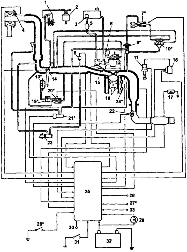
Injection system diagram (5E-FE): 1 - bimetallic solenoid valve; 2 - container with activated carbon; 3 - fuel pump; 4 - intake air temperature sensor; 5 - fuel filter; 6 - fuel pressure regulator; 7 - electro-pneumatic valve; 8 - absolute pressure sensor in the intake manifold; 9 - EGR valve; 10 - vacuum modulator of the exhaust gas recirculation system; 11 - distributor; 12 - electro-pneumatic valve; 13 - throttle valve opening mechanism; 14 - throttle position sensor; 15 - nozzle; 16 - Switch; 17 - speed sensor; 18 - Coolant temperature sensor; 19 - "asymmetrical" pneumatic valve; 20 - electro-pneumatic valve; 21 - Air supply control valve; 22 - oxygen sensor; 23 - additional air supply valve; 24 - coolant temperature switch; 25 - electronic control unit of the engine and automatic transmission; 26 - air conditioner on signal; 27 - signal for switching on the electric fan of the cooling system radiator; 28 - "CHECK" control lamp; 29 Start inhibit switch; 30 - starter; 31 - diagnostic connector; 32 - battery; 33 - headlight on signal.
* - only for models with automatic transmission.