



Share information:
Automatic car gearbox Toyota Corona 9 (T190)

General information about automatic transmission (2WD)
Note: the type of automatic transmission is given on an aluminum plate located on the rear wall of the engine compartment. operation of automatic transmission, replacement of fluids in automatic transmission, main gear...
Note: the type of automatic transmission is given on an aluminum plate located on the rear wall of the engine compartment. operation of automatic transmission, replacement of fluids in automatic transmission, main gear...
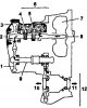
Planetary gearbox (except A132L)
2WD models (except A132L): 1 - intermediate gear driven pinion, 2 - intermediate shaft, 3 - intermediate gear driving pinion, 4 - rear planetary gear set, 5 - front planetary gear set, 6 - planetary gear, 7 - torque...
2WD models (except A132L): 1 - intermediate gear driven pinion, 2 - intermediate shaft, 3 - intermediate gear driving pinion, 4 - rear planetary gear set, 5 - front planetary gear set, 6 - planetary gear, 7 - torque...

Planetary gearbox A132L
Planetary gear (A132L): 1 - intermediate gear driven pinion, 2 - rear planetary gear set epicycle, 3 - first gear and reverse brake (B ₃), 4 - freewheel clutch No.2 (F ₂), 5 - second gear brake (B ₂), 6 - forward clutch...
Planetary gear (A132L): 1 - intermediate gear driven pinion, 2 - rear planetary gear set epicycle, 3 - first gear and reverse brake (B ₃), 4 - freewheel clutch No.2 (F ₂), 5 - second gear brake (B ₂), 6 - forward clutch...

Hydraulic part of the control system (2WD)
The control system includes: an oil pump, a valve block, electromagnetic valves (solenoids), hydraulic accumulators, clutches and brakes. The main pressure in the system is created by the oil pump, it is regulated...
The control system includes: an oil pump, a valve block, electromagnetic valves (solenoids), hydraulic accumulators, clutches and brakes. The main pressure in the system is created by the oil pump, it is regulated...
Electrical part of the control system (A240E, A241E and A245E)
The electric control system for the automatic transmission provides extremely precise control of gear shifting and torque converter locking moments depending on the driving mode and engine operation. In addition, the...
The electric control system for the automatic transmission provides extremely precise control of gear shifting and torque converter locking moments depending on the driving mode and engine operation. In addition, the...

General information about automatic transmission (4WD)
The A540N automatic transmission consists of a torque converter with a lock-up clutch, a 3-speed planetary gearbox with an overdrive planetary row, a transfer case and a control system consisting of hydraulic and...
The A540N automatic transmission consists of a torque converter with a lock-up clutch, a 3-speed planetary gearbox with an overdrive planetary row, a transfer case and a control system consisting of hydraulic and...
Hydraulic part of the control system (4WD)
Transmission The control system includes: an oil pump, a valve block, electromagnetic valves (solenoids), hydraulic accumulators, locking clutches and brakes. The main pressure in the system is created by the oil pump,...
Transmission The control system includes: an oil pump, a valve block, electromagnetic valves (solenoids), hydraulic accumulators, locking clutches and brakes. The main pressure in the system is created by the oil pump,...
Electrical part of the control system (4WD)
The electric control system for the automatic transmission ensures extremely precise control of gear shifting and torque converter locking moments depending on the driving mode and engine operation. In addition, it...
The electric control system for the automatic transmission ensures extremely precise control of gear shifting and torque converter locking moments depending on the driving mode and engine operation. In addition, it...

Working fluid temperature alarm system
The electronic control unit monitors the temperature of the working fluid using a temperature sensor. The temperature of the working fluid may become excessively high when the vehicle is operating under increased load,...
The electronic control unit monitors the temperature of the working fluid using a temperature sensor. The temperature of the working fluid may become excessively high when the vehicle is operating under increased load,...

Checking and adjusting the throttle valve control cable
1. Press the accelerator pedal all the way down and make sure that the control lever rests against the adjusting screw 2. Press the accelerator pedal all the way down and loosen the adjusting nuts. 3. Adjust the cable...
1. Press the accelerator pedal all the way down and make sure that the control lever rests against the adjusting screw 2. Press the accelerator pedal all the way down and loosen the adjusting nuts. 3. Adjust the cable...

Checking and adjusting the automatic transmission control rod
1. When moving the selector from the "N" position to other positions, it should move freely, and the indicator should correctly indicate the selected position. If the indicator incorrectly shows the selected position,...
1. When moving the selector from the "N" position to other positions, it should move freely, and the indicator should correctly indicate the selected position. If the indicator incorrectly shows the selected position,...

Checking and adjusting the engine start inhibit switch
1. Make sure that the engine can only be started when the selector lever is in position "N" or "P". 2. If the engine can be started in other positions, adjust the engine start inhibit switch. a) Loosen the neutral start...
1. Make sure that the engine can only be started when the selector lever is in position "N" or "P". 2. If the engine can be started in other positions, adjust the engine start inhibit switch. a) Loosen the neutral start...
Checking the idle speed (N range)
Check the idle speed with the selector lever in the "N" position and the air conditioner turned off. Idle speed: A241L: 750-850 rpm A240E (4A-FE): 650-950 rpm A241E before 1996: 3S-FE: 450-750 rpm Models since 1996:...
Check the idle speed with the selector lever in the "N" position and the air conditioner turned off. Idle speed: A241L: 750-850 rpm A240E (4A-FE): 650-950 rpm A241E before 1996: 3S-FE: 450-750 rpm Models since 1996:...
Gearbox diagnostics — general information
Note: Malfunctions occurring in the gearbox may be related to either the engine, or the control system, or the gearbox itself. Therefore, before starting the check, it is necessary to determine the area of their...
Note: Malfunctions occurring in the gearbox may be related to either the engine, or the control system, or the gearbox itself. Therefore, before starting the check, it is necessary to determine the area of their...

Self-diagnosis system (A240E, A241E, A245E and A540N)
General information 1. The self-diagnosis function is built into the electronic control unit of the automatic transmission. Using the overdrive mode off indicator, the system can warn the driver about a malfunction in...
General information 1. The self-diagnosis function is built into the electronic control unit of the automatic transmission. Using the overdrive mode off indicator, the system can warn the driver about a malfunction in...
Checking the Overdrive Off Indicator
1. Turn on the ignition. 2. The indicator should light when the overdrive switch is in the "OFF" position. 3. Turn the overdrive switch to the "ON" position: the indicator should go out. If the indicator flashes, this...
1. Turn on the ignition. 2. The indicator should light when the overdrive switch is in the "OFF" position. 3. Turn the overdrive switch to the "ON" position: the indicator should go out. If the indicator flashes, this...
Reading automatic transmission fault codes
1. Turn on the ignition and set the overdrive switch to the "ON" position. Caution: Do not start the engine. 2. Short-circuit the terminals "TE₁" and "E₁" of the diagnostic connector. 3. Read and determine the fault...
1. Turn on the ignition and set the overdrive switch to the "ON" position. Caution: Do not start the engine. 2. Short-circuit the terminals "TE₁" and "E₁" of the diagnostic connector. 3. Read and determine the fault...
Troubleshooting automatic transmission
Note: When fault codes appear (2WD models) no. 37, 38, 42, 61, 62 and 63 or (4WD models) #62, 63 indicator will start flashing immediately to alert the driver. However, a collision or impact may cause the indicator to...
Note: When fault codes appear (2WD models) no. 37, 38, 42, 61, 62 and 63 or (4WD models) #62, 63 indicator will start flashing immediately to alert the driver. However, a collision or impact may cause the indicator to...

Checking gear shifting
Note: This test helps determine whether the problem is electrical or mechanical in the transmission. 1. Disconnect the connector from the solenoid valve block. A241L, A240E, A241E A245E A540H 2. Gear shifting should...
Note: This test helps determine whether the problem is electrical or mechanical in the transmission. 1. Disconnect the connector from the solenoid valve block. A241L, A240E, A241E A245E A540H 2. Gear shifting should...

Checking the automatic transmission and engine control unit
Caution: Do not open the control unit cover unnecessarily, (if you touch the pin of an integrated circuit, it may be damaged by static electricity). Malfunction #1: No switching 1. Warm up the engine to 80°C and the...
Caution: Do not open the control unit cover unnecessarily, (if you touch the pin of an integrated circuit, it may be damaged by static electricity). Malfunction #1: No switching 1. Warm up the engine to 80°C and the...

Checking the voltage at the «TT» terminal
1. Checking the signal from the throttle position sensor. a) Turn on the ignition. Do not start the engine. b) Connect the voltmeter to the diagnostic connector contacts "TT" and "E1". Models before 1996. Models since...
1. Checking the signal from the throttle position sensor. a) Turn on the ignition. Do not start the engine. b) Connect the voltmeter to the diagnostic connector contacts "TT" and "E1". Models before 1996. Models since...

Checking the electrical components of the control system (A240E, A241E, A245E and A540H)
Electrical Component Locations (models since 1996.): 1 - Engine start prohibition switch, 2 - Torque converter lock-up clutch control electromagnetic valve, 3 - Speed sensor No.2, 4 - Engine coolant temperature sensor,...
Electrical Component Locations (models since 1996.): 1 - Engine start prohibition switch, 2 - Torque converter lock-up clutch control electromagnetic valve, 3 - Speed sensor No.2, 4 - Engine coolant temperature sensor,...

Electrical components of automatic transmission A241L
Electrical Components Location (A241L): 1 - overdrive switch, 2 - overdrive solenoid valve, 3 - engine start prohibition switch. 1. Check the engine start inhibit switch. Check the continuity between the connector...
Electrical Components Location (A241L): 1 - overdrive switch, 2 - overdrive solenoid valve, 3 - engine start prohibition switch. 1. Check the engine start inhibit switch. Check the continuity between the connector...
Checking mechanical systems of automatic transmission
Test on a fully braked car (stall test) This test checks the performance of the gearbox and engine by measuring the rotation speed at maximum load in the "D" and "R" ranges. Note: the test should be carried out at...
Test on a fully braked car (stall test) This test checks the performance of the gearbox and engine by measuring the rotation speed at maximum load in the "D" and "R" ranges. Note: the test should be carried out at...
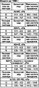
Automatic transmission hydraulic test
Checking the pressure in the main line 1. Preparation: a) Warm up the transmission fluid to operating temperature (50-80°C) b) Unscrew the service plug of the gearbox housing and connect a pressure gauge in its place....
Checking the pressure in the main line 1. Preparation: a) Warm up the transmission fluid to operating temperature (50-80°C) b) Unscrew the service plug of the gearbox housing and connect a pressure gauge in its place....

Test of the interaxle differential lock clutch (A540N)
1. Preparation: a) Warm up the transmission fluid to operating temperature (50-80°C). b) Unscrew the service plug of the gearbox housing and connect a pressure gauge in its place. Caution: Perform the check in pairs -...
1. Preparation: a) Warm up the transmission fluid to operating temperature (50-80°C). b) Unscrew the service plug of the gearbox housing and connect a pressure gauge in its place. Caution: Perform the check in pairs -...

Automatic transmission road test
Note: Before starting the test, warm up the transmission fluid to a temperature of 50-80°C. Test on "D" range Move the selector to the "D" range and press the accelerator pedal all the way down. 1. Check for the...
Note: Before starting the test, warm up the transmission fluid to a temperature of 50-80°C. Test on "D" range Move the selector to the "D" range and press the accelerator pedal all the way down. 1. Check for the...

Throttle valve control cable
Removal 1. Disconnect the control cable from the throttle valve sector or fuel injection pump lever. For diesel engines For petrol engines 2. Remove the engine start inhibit switch lever. a) Disconnect the throttle...
Removal 1. Disconnect the control cable from the throttle valve sector or fuel injection pump lever. For diesel engines For petrol engines 2. Remove the engine start inhibit switch lever. a) Disconnect the throttle...

Rotor of the speed sensor (A240E, A241E before 1996)
Removal Note: Install in the reverse order of removal. 1. Remove the speed sensor and speed sensor rotor. a) Remove the protective plate and speed sensor. Tightening torque during installation is 5.4 Nm. b) Remove the...
Removal Note: Install in the reverse order of removal. 1. Remove the speed sensor and speed sensor rotor. a) Remove the protective plate and speed sensor. Tightening torque during installation is 5.4 Nm. b) Remove the...

Speed controller (A241L, A132L)
Removal Note: Installation is carried out in the reverse order of removal. 1. Disconnect the speedometer cable. 2. Remove the speed controller cover and sealing ring. A241L A132L 3. Remove the speed regulator and thrust...
Removal Note: Installation is carried out in the reverse order of removal. 1. Disconnect the speedometer cable. 2. Remove the speed controller cover and sealing ring. A241L A132L 3. Remove the speed regulator and thrust...

Speed sensor #2 (A245E)
Replacement 1. Disconnect the sensor connector. 2. Remove speed sensor #2. a) Unscrew the bolt and remove the sensor. b) Remove the sealing ring from the sensor. 3. Install speed sensor #2. a) Lubricate the new sealing...
Replacement 1. Disconnect the sensor connector. 2. Remove speed sensor #2. a) Unscrew the bolt and remove the sensor. b) Remove the sealing ring from the sensor. 3. Install speed sensor #2. a) Lubricate the new sealing...

Drive shaft seals (front wheel drive)
Removal 1. Drain the transmission fluid. 2. Remove the lower engine guard. 3. Remove the right and left drive shafts. 4. Remove the left and right drive shaft seals using a puller. Installation 1. Install the left drive...
Removal 1. Drain the transmission fluid. 2. Remove the lower engine guard. 3. Remove the right and left drive shafts. 4. Remove the left and right drive shaft seals using a puller. Installation 1. Install the left drive...

Replacing the output shaft seal (rear wheel drive) (A540N)
1. Drain the transmission fluid. 2. Remove the driveshaft. 3. Using a puller, remove the output shaft seal. 4. Install the output shaft seal a) Lubricate the working edge of the seal with consistent grease b) Using a...
1. Drain the transmission fluid. 2. Remove the driveshaft. 3. Using a puller, remove the output shaft seal. 4. Install the output shaft seal a) Lubricate the working edge of the seal with consistent grease b) Using a...
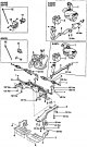
Removal and installation the gearbox (2WD models, before 1996)
2WD models before 1996: 1 - Air intake and air filter, 2 - Battery, 3 - Downpipe, 4 - Left drive shaft, 5 - Engine mount central support beam, 6 - Beam guard, 7 - Engine guard cover, 8 - Cross beam, 9 - Right drive...
2WD models before 1996: 1 - Air intake and air filter, 2 - Battery, 3 - Downpipe, 4 - Left drive shaft, 5 - Engine mount central support beam, 6 - Beam guard, 7 - Engine guard cover, 8 - Cross beam, 9 - Right drive...
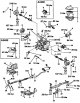
Removal and installation the gearbox (2WD models, since 1996)
2WD Models Since 1996 1 - Cotter Pin, 2 - Lock Nut Cap, 3 ~ Left Drive Shaft, 4 - Snap Ring, 5 - Starter, 6 - Left Engine Mount Bracket, 7 - Air Intake & Air Cleaner, 8 - Rear Engine Mount Bracket, 9 - Torque Converter,...
2WD Models Since 1996 1 - Cotter Pin, 2 - Lock Nut Cap, 3 ~ Left Drive Shaft, 4 - Snap Ring, 5 - Starter, 6 - Left Engine Mount Bracket, 7 - Air Intake & Air Cleaner, 8 - Rear Engine Mount Bracket, 9 - Torque Converter,...

Gearbox assembly (4WD models)
Note: Removal and installation of the gearbox for 4WD models is carried out in the same way as removal and installation for 2WO models, taking into account the design features. 4WD models: 1 - central bracket, 2 -...
Note: Removal and installation of the gearbox for 4WD models is carried out in the same way as removal and installation for 2WO models, taking into account the design features. 4WD models: 1 - central bracket, 2 -...

Checking the torque converter and torque converter drive plate
1. If the transmission fluid is contaminated, flush the torque converter and the transmission fluid cooler 2. Checking the freewheel clutch. a) Install the special tool into the inner race of the freewheel clutch. b)...
1. If the transmission fluid is contaminated, flush the torque converter and the transmission fluid cooler 2. Checking the freewheel clutch. a) Install the special tool into the inner race of the freewheel clutch. b)...

Transfer case (only for A540H)
Transfer case: 1 - Transfer case cover holder; 2 - sealing ring; 3 - mounting pin; 4 - driven gear of the pump drive; 5 - sealing ring; 6 - filter; 7 - shaft of the main transmission drive gear assembly; 8 - gasket; 9 -...
Transfer case: 1 - Transfer case cover holder; 2 - sealing ring; 3 - mounting pin; 4 - driven gear of the pump drive; 5 - sealing ring; 6 - filter; 7 - shaft of the main transmission drive gear assembly; 8 - gasket; 9 -...
This section is available on: russian, bulgarian, belarusian, ukrainian, serbian, croatian, romanian, polish, slovak, hungarian
Similar sections for other Toyota models
➥ Automatic gearbox Toyota Cruiser 100 (1998-2007)
➥ Automatic gearbox Toyota Duet (1998-2004)
➥ Automatic gearbox Toyota Carina T190 (1992-1996)
➥ Automatic gearbox Toyota Corolla E80 (1983-1990)
➥ Automatic gearbox Toyota Camry XV10 (1991-1996)
➥ Automatic gearbox Toyota Highlander 1 (2000-2007, petrol)
Link in different formats to this article
TEXTHTMLBB Code
- General information
- User manual
- Maintenance
- Power unit
- Engines 3S-FE/GE and 4S-FE
- Engines 4A-FE and 7A-FE
- Engines 5E-FE
- Diesel engines 2C and 2C-T
- Engine overhaul
- Cooling system
- Lubrication system
- Fuel injection (petrol)
- Control system (petrol)
- Fuel system (diesel)
- Turbo diesel
- Ignition system
- Engine electrical equipment
- Transmission
- Clutch
- Mechanical gearbox
- Automatic gearbox
- Drive shafts and cardan
- Chassis, running gear
- Front suspension
- Rear suspension
- Steering
- Brake system
- Body and interior
- Body and interior elements
- Doors, windows and locks
- Heating and air conditioning
- Electrical equipment
- Equipment and devices
- Lighting and signaling
- Electrical circuits