



Share information:
Electrical Equipment and Appliances Toyota Corona 9 (T190)

Electrical Equipment — Safety Precautions
1. Before working on electrical equipment, disconnect the cable from the negative terminal of the battery. 2. If it is necessary to disconnect the battery for a check or repair, be sure to first disconnect the cable...
1. Before working on electrical equipment, disconnect the cable from the negative terminal of the battery. 2. If it is necessary to disconnect the battery for a check or repair, be sure to first disconnect the cable...

Replacing fuses
1. Before servicing, turn off the ignition and all electrical devices. 2. Install fuses with the specified amperage rating only. Note: Do not use a fuse with a higher amperage rating or any other objects ("bugs") in...
1. Before servicing, turn off the ignition and all electrical devices. 2. Install fuses with the specified amperage rating only. Note: Do not use a fuse with a higher amperage rating or any other objects ("bugs") in...

Identification of connectors
1. The contacts in the female part of the connector are numbered from the top left to the bottom right. 2. The contacts of the plug part of the connector are numbered from the upper right to the lower left edge. Note:...
1. The contacts in the female part of the connector are numbered from the top left to the bottom right. 2. The contacts of the plug part of the connector are numbered from the upper right to the lower left edge. Note:...
SRS System — General Information and Precautions
General information TOYOTA vehicles are equipped with an airbag system (SRS). Along with seat belts, this system increases the safety of the driver and passenger in the event of an accident. In the event of a collision,...
General information TOYOTA vehicles are equipped with an airbag system (SRS). Along with seat belts, this system increases the safety of the driver and passenger in the event of an accident. In the event of a collision,...

SRS manufactured before 1996 — device
System components: 1 - airbag, 2 - igniter, 3 - sensor, 4 - fuse bracket, 5 - fuse bolt, 6 - steering wheel pad, 7 - steering wheel SRS Sensor: 1 - Pressure spring, 2 - Pressure pin, 3 - Lever, 4 - Igniter needle, 5 -...
System components: 1 - airbag, 2 - igniter, 3 - sensor, 4 - fuse bracket, 5 - fuse bolt, 6 - steering wheel pad, 7 - steering wheel SRS Sensor: 1 - Pressure spring, 2 - Pressure pin, 3 - Lever, 4 - Igniter needle, 5 -...

SRS before 1996 — steering wheel pad
Steering wheel cover: 1 - Steering wheel bolt, 2 - Steering wheel trim, 3 - Lower cover N83, 4 - Lower cover No.2, 5 - Fuse bolt, 6 - Fuse bracket Removal the steering wheel cover 1. Using a screwdriver, remove the...
Steering wheel cover: 1 - Steering wheel bolt, 2 - Steering wheel trim, 3 - Lower cover N83, 4 - Lower cover No.2, 5 - Fuse bolt, 6 - Fuse bracket Removal the steering wheel cover 1. Using a screwdriver, remove the...

SRS since 1996 — driver's airbag
Driver's airbag: 1 - steering wheel cover, 2 - steering wheel, 3 - upper steering column cover, 4 - combination switch (with spiral wire), 5 - lower steering wheel cover Models produced since 1996 are equipped with...
Driver's airbag: 1 - steering wheel cover, 2 - steering wheel, 3 - upper steering column cover, 4 - combination switch (with spiral wire), 5 - lower steering wheel cover Models produced since 1996 are equipped with...

SRS since 1996 — passenger airbag
Passenger airbag: 1 - passenger airbag, 2 - radio, 3 - glove box lid, 4 - glove box lid hinges, 5 - air conditioning control panel, 6 - central trim panel, 7 - lower trim panel Removal the passenger airbag 1. Disconnect...
Passenger airbag: 1 - passenger airbag, 2 - radio, 3 - glove box lid, 4 - glove box lid hinges, 5 - air conditioning control panel, 6 - central trim panel, 7 - lower trim panel Removal the passenger airbag 1. Disconnect...
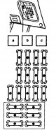
Relays and fuses
Fuse box #1 Note: Fuses 14. 18, circled in the figure, can be separated into a separate block located under the main one. Fuse and Relay Box #2 Relay Block #5
Fuse box #1 Note: Fuses 14. 18, circled in the figure, can be separated into a separate block located under the main one. Fuse and Relay Box #2 Relay Block #5

Ignition switch
Ignition switch connector Checking the ignition switch If the conductivity does not match the table, replace the ignition switch. Checking the sensor for a key left in the lock 1. Check for continuity between terminals...
Ignition switch connector Checking the ignition switch If the conductivity does not match the table, replace the ignition switch. Checking the sensor for a key left in the lock 1. Check for continuity between terminals...

Combination switch — design description
Models before 1996: 1 - windscreen wiper and washer switch,:8 - switch housing, 3 - ball holder, 4 - ball, 5 - spring, 6 - light switch and headlight and turn signal switch Models after 1996: 1 - windshield wiper and...
Models before 1996: 1 - windscreen wiper and washer switch,:8 - switch housing, 3 - ball holder, 4 - ball, 5 - spring, 6 - light switch and headlight and turn signal switch Models after 1996: 1 - windshield wiper and...
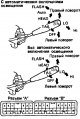
Checking the combination switch
Models before 1996 Checking the light switch Switch position Conclusions OFF no conductivity TAIL (Dimensions and lighting) A2-A11 HEAD (Headlights) A2-A11-A13 AUTO* A11-B19 Checking the headlight switch Switch position...
Models before 1996 Checking the light switch Switch position Conclusions OFF no conductivity TAIL (Dimensions and lighting) A2-A11 HEAD (Headlights) A2-A11-A13 AUTO* A11-B19 Checking the headlight switch Switch position...

Checking door limit switches
1. Check for continuity between the terminal and the body when the switch is in the "ON" position (button released). 2. Make sure there is no conductivity between the terminal and the housing when the switch is in the...
1. Check for continuity between the terminal and the body when the switch is in the "ON" position (button released). 2. Make sure there is no conductivity between the terminal and the housing when the switch is in the...

Windscreen wipers and washers — check
Checking the combination switch For disassembly of the combination switch, see above. Models before 1996 Check the conductivity between the connector pins according to the table. Models after 1996 If the conductivity is...
Checking the combination switch For disassembly of the combination switch, see above. Models before 1996 Check the conductivity between the connector pins according to the table. Models after 1996 If the conductivity is...

Headlight Washer — Check
Checking the headlight washer switch 1. Check for conductivity between terminals "2" and "3" (backlight) in both switch positions. 2. Check for conductivity between terminals "1" and "4" in the on position and no...
Checking the headlight washer switch 1. Check for conductivity between terminals "2" and "3" (backlight) in both switch positions. 2. Check for conductivity between terminals "1" and "4" in the on position and no...


Checking the speedometer sensor
Checking the speed sensor. a) Connect the battery to terminals "1" (+) and "2" (-). b) Connect the tester to terminals "3" (+) and "2" (-) of the connector. c) Turn the shaft. d) Check for a voltage change from 0 to 11...
Checking the speed sensor. a) Connect the battery to terminals "1" (+) and "2" (-). b) Connect the tester to terminals "3" (+) and "2" (-) of the connector. c) Turn the shaft. d) Check for a voltage change from 0 to 11...

Checking the tachometer
Checking the tachometer on a car a) Connect the adjustment control tachometer and start the engine. Note: Reversing the polarity when connecting the tachometer will result in failure of the transistors and diodes. b)...
Checking the tachometer on a car a) Connect the adjustment control tachometer and start the engine. Note: Reversing the polarity when connecting the tachometer will result in failure of the transistors and diodes. b)...

Fuel level indicator
Checking the fuel gauge 1. Disconnect the connector from the fuel level sensor. 2. Turn on the ignition and check that the fuel gauge pointer points to the "EMPTY" mark. 3. Connect a 3W test lamp between terminals "2"...
Checking the fuel gauge 1. Disconnect the connector from the fuel level sensor. 2. Turn on the ignition and check that the fuel gauge pointer points to the "EMPTY" mark. 3. Connect a 3W test lamp between terminals "2"...

Coolant temperature indicator
Checking the operation of the temperature indicator 1. Disconnect the connector from the temperature sensor. 2. Turn on the ignition. The temperature gauge arrow should point to the "COOL" position. 3. Using a 3 W test...
Checking the operation of the temperature indicator 1. Disconnect the connector from the temperature sensor. 2. Turn on the ignition. The temperature gauge arrow should point to the "COOL" position. 3. Using a 3 W test...

Oil pressure warning light
1. Checking the indicator lamp. a) Disconnect the connector from the test lamp and ground the connector on the wire side. b) Turn on the ignition. Check that the indicator lamp lights up. If the indicator lamp does not...
1. Checking the indicator lamp. a) Disconnect the connector from the test lamp and ground the connector on the wire side. b) Turn on the ignition. Check that the indicator lamp lights up. If the indicator lamp does not...

Parking brake and low brake fluid level indicator
1. Checking the indicator lamp. a) Disconnect the connector from the parking brake switch and the low brake fluid level switch. b) Ground the sensor connector (engaging the parking brake) from the wire side. c) Start...
1. Checking the indicator lamp. a) Disconnect the connector from the parking brake switch and the low brake fluid level switch. b) Ground the sensor connector (engaging the parking brake) from the wire side. c) Start...
Checking the low engine oil level sensor
1. Checking the sensor. a) Check for continuity between the terminals in each sensor position. b) Heat the sensor to a temperature above 60°C in an oil bath. c) Check for continuity between the terminals when the sensor...
1. Checking the sensor. a) Check for continuity between the terminals in each sensor position. b) Heat the sensor to a temperature above 60°C in an oil bath. c) Check for continuity between the terminals when the sensor...
Open or ajar door warning system
1. Check the limit switches on the doors (see above). 2. Check the indicator lamp. a) Disconnect the connector from the limit switch and ground terminal "1" of the connector on the wire side. Check that the indicator...
1. Check the limit switches on the doors (see above). 2. Check the indicator lamp. a) Disconnect the connector from the limit switch and ground terminal "1" of the connector on the wire side. Check that the indicator...

Checking the seat belt sensor
1. Check for continuity between the terminals of the sensor connector in the belt buckle with the belt inserted. 2. Check for conductivity without the belt in the lock. If the conductivity does not match the...
1. Check for continuity between the terminals of the sensor connector in the belt buckle with the belt inserted. 2. Check for conductivity without the belt in the lock. If the conductivity does not match the...

Rear door and mirror heaters
Checking the operation of the heater switch Models before 1996 1. Check the conductivity between the terminals of the switch connector. a) Check for absence of conductivity between terminals "2" and "3" in the "OFF"...
Checking the operation of the heater switch Models before 1996 1. Check the conductivity between the terminals of the switch connector. a) Check for absence of conductivity between terminals "2" and "3" in the "OFF"...

Electric windows — check
Checking the main switch 1. Check the main switch circuit according to the table. If the conductivity does not match the table, replace the switch. 2. Checking the main switch backlight (models before 1996). a) Set the...
Checking the main switch 1. Check the main switch circuit according to the table. If the conductivity does not match the table, replace the switch. 2. Checking the main switch backlight (models before 1996). a) Set the...

Central locking — check
Checking the main switch Check the main switch circuit as shown in the table. If the conductivity is different from the specified value, replace the switch. Checking the central lock switch (in the door lock) Models...
Checking the main switch Check the main switch circuit as shown in the table. If the conductivity is different from the specified value, replace the switch. Checking the central lock switch (in the door lock) Models...

Electric Sunroof — Check
Checking the switch Checking limit switches Checking the operation of the electric motor 1. Connect the "+" of the battery to terminal "1" and the "-" to terminals "2" and "5" of the connector: the motor armature should...
Checking the switch Checking limit switches Checking the operation of the electric motor 1. Connect the "+" of the battery to terminal "1" and the "-" to terminals "2" and "5" of the connector: the motor armature should...

External mirror adjustment system
Checking the conductivity of the mirror position adjustment switch Without folding mirrors With folding mirrors Check for continuity between terminals "4" and "10" with the mirror folding switch pressed. Models after...
Checking the conductivity of the mirror position adjustment switch Without folding mirrors With folding mirrors Check for continuity between terminals "4" and "10" with the mirror folding switch pressed. Models after...

Seat Heaters — Check
Checking the switch 1. Check the conductivity of the switch according to the table. If the conductivity is not as described, replace the switch. 2. Checking the heater indicator lights. a) Connect the battery to...
Checking the switch 1. Check the conductivity of the switch according to the table. If the conductivity is not as described, replace the switch. 2. Checking the heater indicator lights. a) Connect the battery to...

Antenna Drive — Check
Checking the antenna motor 1. Connect the battery to terminals "2" (+) and "3" (-) of the connector. 2. Check that the engine is running (the antenna extends). Note: This test should be carried out for no more than 3 -...
Checking the antenna motor 1. Connect the battery to terminals "2" (+) and "3" (-) of the connector. 2. Check that the engine is running (the antenna extends). Note: This test should be carried out for no more than 3 -...
This section is available on: russian, bulgarian, belarusian, ukrainian, serbian, croatian, romanian, polish, slovak, hungarian
Link in different formats to this article
TEXTHTMLBB Code
- General information
- User manual
- Maintenance
- Power unit
- Engines 3S-FE/GE and 4S-FE
- Engines 4A-FE and 7A-FE
- Engines 5E-FE
- Diesel engines 2C and 2C-T
- Engine overhaul
- Cooling system
- Lubrication system
- Fuel injection (petrol)
- Control system (petrol)
- Fuel system (diesel)
- Turbo diesel
- Ignition system
- Engine electrical equipment
- Transmission
- Clutch
- Mechanical gearbox
- Automatic gearbox
- Drive shafts and cardan
- Chassis, running gear
- Front suspension
- Rear suspension
- Steering
- Brake system
- Body and interior
- Body and interior elements
- Doors, windows and locks
- Heating and air conditioning
- Electrical equipment
- Equipment and devices
- Lighting and signaling
- Electrical circuits