
Examination
Chock the front wheels to prevent the vehicle from moving. Raise the rear of the car and place it on stands. Release the parking brake lever and place the shift lever in neutral.
From under the car, inspect the driveshaft for dents or cracks. If there is any damage, replace the cardan shaft.
Check for leaks at the connections between the front and rear of the driveshaft to the gearbox and to the rear final drive. The presence of leaks in the front indicates wear or a defect in the gearbox cuff, and leaks in the rear indicate failure of the cuff of the rear final drive.
While the assistant rotates the rear wheel, check the condition of the universal joints, which should rotate smoothly, without jamming and visible play. If the driveshaft support bearing makes noise, it is worn or damaged and needs to be replaced. Also check the condition of the rubber bearing mount for delamination and cracks.
Check up a condition of universal joints at a motionless cardan shaft, having grasped it with two hands and trying to turn in one and another party. Any play indicates wear on the joints, in which case the front or rear of the driveshaft must be replaced.
Finally, check the propeller shaft mounting bolts for tightness.
Removing
Chock the front wheels to prevent the vehicle from moving. Raise the rear of the car and place it on stands. Release the parking brake lever and place the shift lever in neutral.
Use paint or a marker to apply alignment marks to the flange of the main reverse gear and the propeller shaft flange. This is necessary to reinstall the shaft to its original position, to maintain the balance of the shaft.
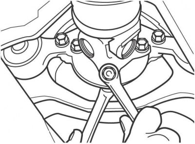
Pic. 10.10. Removing the bolts securing the rear universal joint of the propeller shaft to the flange of the main reverse gear
Remove the nuts and bolts securing the rear universal joint of the propeller shaft to the flange of the main reverse gear (pic. 10.10). To access the nuts and bolts, rotate the cardan shaft.
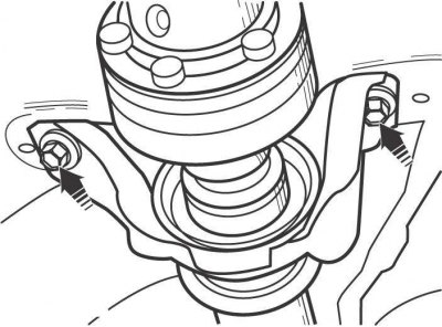
Pic. 10.11. Arrangement of bolts of fastening of an arm of the basic bearing of a cardan shaft to the bottom of the car
Turn out bolts of fastening of an arm of the basic bearing of a cardan shaft to the bottom of the car (pic. 10.11).
Remove the front side of the driveshaft from the transmission and remove the driveshaft assembly from under the vehicle.
Installation
Lubricate the sealing lips of the gearbox seal. Insert the front part of the driveshaft into the transmission and screw, but do not tighten, the bolts securing the driveshaft support bearing bracket to the bottom of the vehicle.
Connect the propeller shaft rear universal joint to the main reverse gear flange, aligning the marks made before removal. Secure it with nuts and bolts and tighten them to 74 Nm.
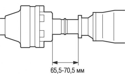
Pic. 10.12. Distance between the hinge cover and the protrusion on the back of the driveshaft
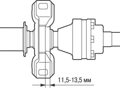
Pic. 10.13. Distance between the back of the support bearing and the back of the rubber support
Adjust the propeller shaft bearing bracket so that the distance between the hinge cover and the protrusion on the rear of the propeller shaft is between 65.5-70.5 mm, and the distance between the rear of the thrust bearing and the rear of the rubber support should be within 11.5–13.5 mm (pic. 10.12, 10.13). Tighten the propeller shaft support bearing bracket bolts to 37 Nm.