
ABS modulator
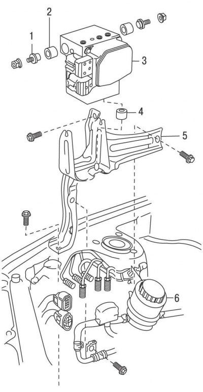
Pic. 11.10. ABS modulator for models up to 2001 (modulator of 1996 4WD models has minor differences): 1 - bolt; 2, 4 - pillow; 3 – ABS modulator; 5 – modulator bracket; 6 – a reservoir of the amplifier of a steering
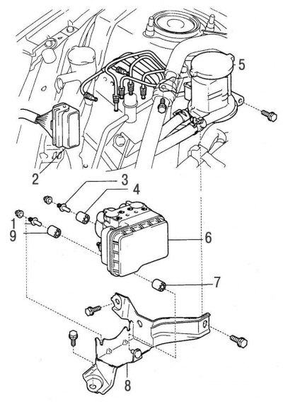
Pic. 11.11. ABS modulator models since 2001: 1 - bolt; 2 - electrical connector of the modulator; 3 - bolt; 4, 9 - pillows; 5 – a reservoir of the amplifier of a steering with an arm; 6 – ABS modulator; 7 - pillow; 8 – modulator bracket
Place a clean rag under the modulator to collect the leaked brake fluid. Using a wrench, unscrew the nuts and disconnect 6 tubes from the ABS modulator (pic. 11.10, 11.11).
Remove and set aside the power steering compensation tank. On models prior to 2001, remove the bolt and disconnect the power steering tube retainer from the ABS modulator bracket.
Disconnect the electrical connector from the ABS modulator.
Turn out bolts and remove the ABS modulator together with an arm.
If necessary, unscrew the bolts and remove the ABS modulator from the bracket.
Install in the reverse order of removal.
After installation, bleed the hydraulic brake system.
Front wheel speed sensor
Apply the parking brake and chock the rear wheels.
Loosen the front wheel nuts. Raise the front of the car and place it on stands. Remove the front wheel and front wheel arch mudguard.
Track the location of the electrical connector along the sensor wire and disconnect the connector.
Turn out bolts of fastening of a wire of the gauge.
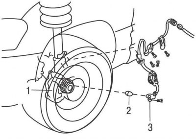
Pic. 11.3. Front speed sensor: 1 – a rotor of the gauge of frequency of rotation of a forward wheel; 2 - bushing; 3 - front wheel speed sensor
Unscrew the bolt and remove the wheel speed sensor and bushing from the steering knuckle (see fig. 11.3).
Install in the reverse order of removal, taking into account the following.
Tighten the sensor mounting bolt to 8 Nm.
Rear wheel speed sensor on all models, except models with one drive axle from 2001
Remove the rear seat cushion and backrest.
Disconnect the electrical connector, then push the O-ring and sensor wire out of the floor trough.
Block the front wheels with chocks. Loosen rear wheel nuts. Raise the rear of the car and place it on stands.
Remove the bolt securing the parking brake cable to the rear suspension arm.
Turn out a bolt of fastening of a plait of wires to a protective arm.
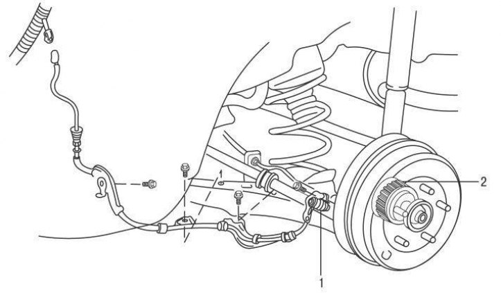
Pic. 11.4. Rear speed sensor on all models up to 2001 and on all-wheel drive models since 2001: 1 - rear wheel speed sensor; 2 – a rotor of the gauge of frequency of rotation of a back wheel
Remove the bolt and remove the wheel speed sensor and bushing from the rear beam (pic. 11.4).
Install in the reverse order of removal, taking into account the following.
Tighten the sensor mounting bolt to 8 Nm.
Speed sensor rear wheel on models with one driving axle release since 2001
Block the front wheels with chocks. Loosen rear wheel nuts. Raise the rear of the car and place it on stands.
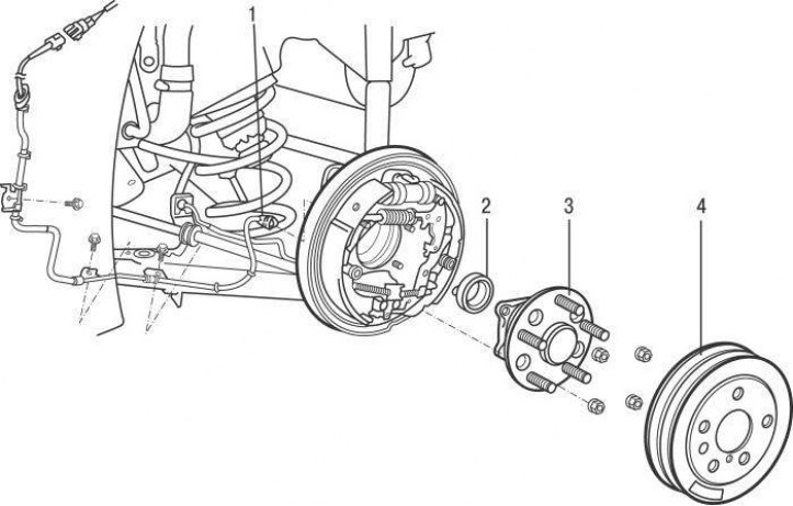
Pic. 11.5. Rear speed sensor on single drive axle models since 2001: 1 - electrical connector; 2 – the gauge of frequency of rotation of a back wheel; 3 - hub; 4 - brake drum
Disconnect the electrical connector from the rear wheel speed sensor (pic. 11.5).
Remove the rear wheel hub along with the bearing.
Use a hammer to knock the sensor out of the rear hub support through the tubular mandrel.
Install in the reverse order of removal, taking into account the following.
To install a new sensor, you need a press and an adapter that is installed on the outer ledge of the sensor.
Deceleration sensor
Remove the rear of the center console.
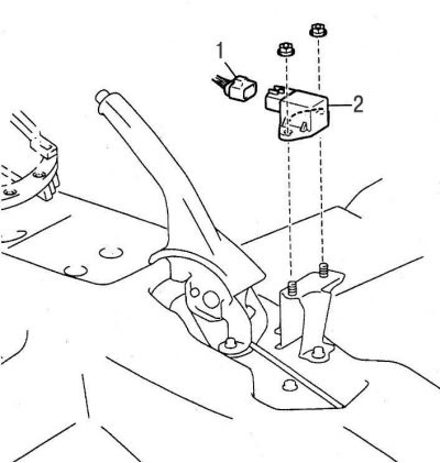
Pic. 11.12. Deceleration sensor: 1 - electrical connector; 2 - deceleration sensor
Disconnect the electrical connector from the sensor, remove the 2 nuts and remove the deceleration sensor (pic. 11.12).
Install in the reverse order of removal.