
Company Honda Company Ford Company Skoda Company Kia Company Mazda Company Mercedes Company Renault
English Русский
Български
Беларускі
Український
Српски
Hrvatski
Română
Polski
Slovenský
Magyar
Bookmark Articles Sitemap Contacts
ToyotaMan.ru


Camry Corolla Corona Carina Land Cruiser Highlander 4Runner RAV4 Others
RAV 4 XA20 (2000-2005) RAV 4 XA10 (1994-2000)

Checking and replacing the brake booster [Toyota RAV4 XA10]

  • Main
  • RAV4
  • XA10 (1994-2000)
  • Chassis, running gear
  • Brake system
  • Checking and replacing the brake booster
0
Contents: Examination ↓ Removal ↓ Installation ↓

Examination


The brake booster increases the force applied to the brake pedal, thereby making the vehicle easier to control. The operating principle of the vacuum brake booster is based on the use of vacuum in the intake manifold. If the vacuum booster fails, the performance of the brake system is not affected, but significantly more force must be applied to press the brake pedal.

Press the brake pedal several times with the engine off to create a uniform pressure in the vacuum booster cavities, close to atmospheric pressure. At the same time, by the force applied to the pedal, determine whether the valve body is jammed. Stop the brake pedal in the middle of its travel and start the engine. If the vacuum booster is working properly, the brake pedal should go down after starting the engine. If the pedal does not move, check the vacuum hose tip fastening, the tip flange connection in the booster, the condition of the hose and fitting.

Wait two minutes and turn off the engine. Press the brake pedal. With each subsequent press, the pedal should become harder and the pedal travel should decrease.

Removal


Disconnect the vacuum hose connecting the inlet manifold and the brake booster. Be careful not to damage the vacuum hose when removing it from the vacuum booster valve fitting.

Remove the brake master cylinder. On pre-2001 models, remove the air intake duct and fuse/relay box.

Remove the lower trim panel from the left side of the instrument panel.


Remove the brake pedal return spring.
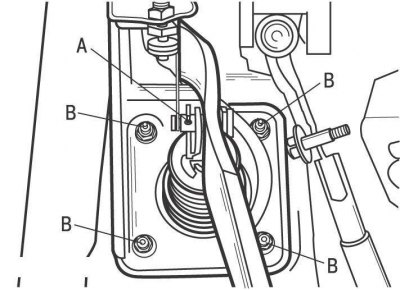


Figure 11.39. Brake booster mounting: A – pin; B – nuts


Disconnect the brake booster pushrod from the top of the brake pedal by removing the cotter pin and pulling out the pin (figure 11.39).

From inside the vehicle, unscrew the four nuts securing the brake booster to the engine compartment bulkhead and remove the brake booster from the engine compartment.

Installation


Installation is carried out in the reverse order of removal, taking into account the following.

If a new vacuum booster is being installed, check the tappet clearance as follows:
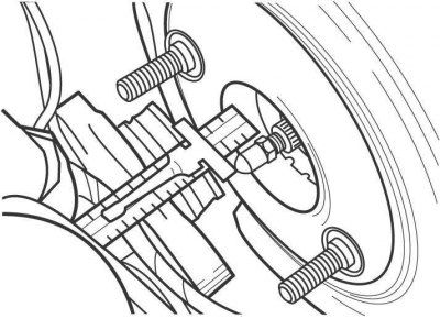


Figure 11.40. Measuring the brake booster tappet protrusion (dimension A)

  • measure the distance the brake booster pushrod protrudes from the master cylinder mating surface (figure 11.40), and write it down as size A;
  • measure the distance from the flange end to the mating surface of the master cylinder and record it as dimension B;
  • measure the distance from the flange to the master cylinder piston and record it as dimension C;
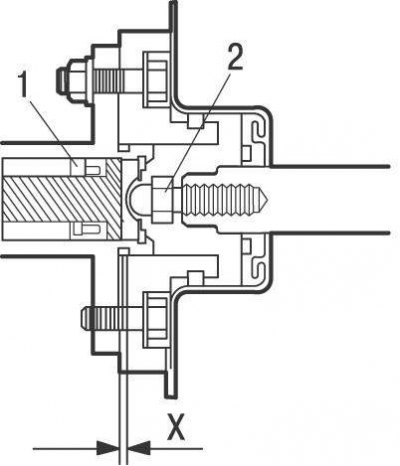


Figure 11.41. Clearance between the pusher (2) of the brake booster and the piston (1) of the brake master cylinder: X = 0 mm


  • subtract dimension B from dimension A, then subtract dimension C from the resulting value (A - B) to get gap X (figure 11.41) pusher 2, which should be equal to 0. If the gap value is negative, i.e. the vacuum booster pusher presses on piston 1 of the master brake cylinder, then constant braking of the wheels will occur. If there is a gap, the brake pedal travel will increase when braking.

If the gap size does not correspond to the required value, then adjust it by changing the length of the pusher. Use pliers to hold the brake booster pushrod from turning and use a wrench to screw the pushrod head in or out.

After installing the master cylinder and connecting the brake lines to it, adjust the brake pedal height and bleed the hydraulic brake system.
This article is available at: russian, bulgarian, belarusian, ukrainian, serbian, croatian, romanian, polish, slovak, hungarian
The article material has been checked: Kolokoltsev Grigory
Share information:
◀ Previous
RAV 4 XA10: Brake system
Next ▶

Bleeding the hydraulic brake system
Replacing brake pipes and hoses
Replacing the brake fluid reservoir sealing rings
Replacing the brake master cylinder
Replacing the wheel brake cylinder
Adjusting the parking brake
Replacing the parking brake cables
Adjusting the brake pedal position
Checking and replacing the brake light switch
Similar articles on other Toyota models

➥ Checking, removing and installing the brake booster Toyota Camry XV30 (2001-2006)
➥ Checking the brake booster assembly Toyota Corolla Verso 3 (2004-2009)
➥ Checking the brake booster check valve Toyota Carina T190 (1992-1996)
➥ Checking the condition and replacing brake lines and hoses Toyota Cruiser 100 (1998-2007)
➥ Vacuum brake booster — checking, removal and installation Toyota Highlander 1 (2000-2007, petrol)
➥ Brake Light Switch — Checking and Replacing Toyota 4Runner N120 (1989-1995)
Link in different formats to this article
Comments and feedback from visitors
No comments yet


Add two numbers 24 + 49


RAV 4 XA20 (2000-2005) 
  • General information
  • Introduction to manual
  • User manual
  • Daily care
  • Maintenance (petrol)
  • Maintenance (diesel)
  • Troubleshooting
  • Power unit
  • Gasoline engines (before 2000)
  • Petrol engines (since 2001)
  • Diesel engines
  • Engine overhaul
  • Cooling and heating
  • Fuel system (petrol)
  • Fuel system (diesel)
  • Engine electrical equipment
  • Control system (petrol)
  • Control system (diesel)
  • Transmission
  • Manual gearbox
  • Automatic gearbox
  • Clutch and drive shafts
  • Chassis, running gear
  • Brake system
  • Front suspension
  • Rear suspension
  • Steering system
  • Body and interior
  • Exterior (external elements)
  • Interior (internal elements)
  • Doors, locks and windows
  • Electrical equipment
  • Equipment and devices
  • Electrical circuits
RAV 4 XA10 (1994-2000) 
  • General information
  • User manual
  • Maintenance
  • Power unit
  • Petrol engine 3S-FE
  • Petrol engine 1AZ-FE
  • Engine overhaul
  • Cooling and air conditioning
  • Fuel and exhaust system
  • Ignition system
  • Toxicity reduction system
  • Transmission
  • Clutch
  • Mechanical gearbox
  • Automatic gearbox
  • Cardan and drive shafts
  • Chassis, running gear
  • Brake system
  • Car suspension
  • Steering
  • Body and interior
  • Exterior (external elements)
  • Interior (internal elements)
  • Doors, locks and windows
  • Electrical equipment
  • Equipment and devices
  • Power devices
  • Electrical circuits
ToyotaMan.ru © 2018–2026 • Mobile version • Interesting about Toyota • Administration • Sitemap: EN BG BY UA RS HR RO PL SK HU • Search system • Bookmark
Camry Vista-V40 • Camry XV10 • Camry XV20 • Camry XV30 • Corolla Verso-AR10 • Corolla E80 • Corona T190 • Carina T170 • Carina T190 • Land Cruiser J70 (diesel) • Land Cruiser J60 (petrol) • Land Cruiser J100 • Highlander XU20 (petrol) • 4Runner N120 • RAV4 XA10 • RAV4 XA20 • Duet M100 • Dyna Y50 •
We require cookies to enable some interactive features. Is that ok with you?