
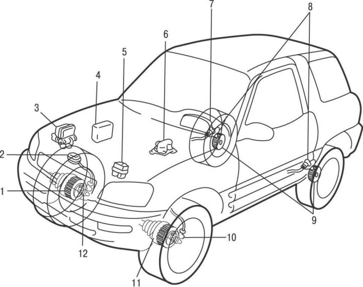
Pic. 11.1. The location of the elements of the anti-lock braking system on cars before 2001: 1, 11 – rotors of front wheel speed sensors; 2 - diagnostic connector; 3 – pressure modulator; 4 - electronic control unit ABS; 5 - ABS relay; 6 - deceleration sensor; 7 - control lamp ABS; 8 – back sensors of frequency of rotation of back wheels; 9 – rotors of sensors of frequency of rotation of back wheels; 10.12 - front wheel speed sensors
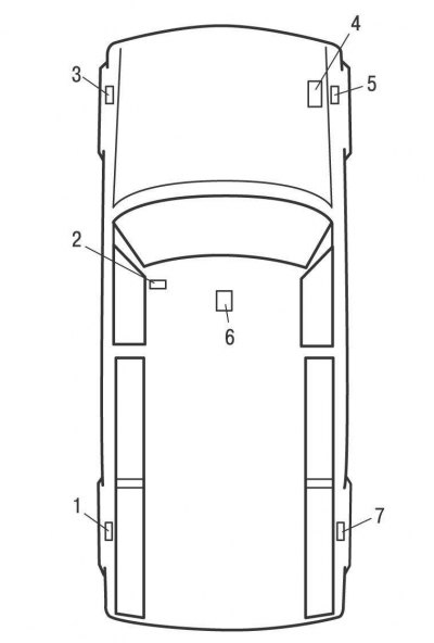
Pic. 11.2. The location of the elements of the anti-lock braking system on cars produced since 2001: 1,3, 5, 7 - wheel speed sensors; 2 - diagnostic connector; 4 – pressure modulator; 6 - deceleration sensor
Anti-lock braking system (pic. 11.1, 11.2) limits the pressure generated in the hydraulic brake actuator so that the amount of slip is kept near the optimum. The action of this system is immediate and independent for each wheel. The system immediately responds to every change in the friction coefficient of the surface and vehicle load.
The anti-lock braking system prevents the wheels from locking during heavy braking, so that the vehicle remains steerable, even with poor traction in rain and snow. The traction force between the wheels and the road is greater when the wheels continue to rotate during braking. RPM sensors, one for each wheel, measure wheel speed. Based on the signals from the speed sensors, the electronic control unit calculates an average speed that approximately corresponds to the speed of the vehicle. By comparing the rotation speed of each individual wheel with the average calculated speed, the electronic unit determines the slip state of each wheel and determines which wheel is in the pre-lock state.
When any of the four speed sensors transmits a lock signal to the corresponding wheel, the ECM immediately sends a close signal to the corresponding inlet solenoid valve, which shuts off the brake fluid supply through the line to the wheel brake, and the braking force remains constant. If the sliding continues, the release valve opens and the pressure in the hydraulic system of this brake decreases - the wheel is not braked. Excess brake fluid returns to the reservoir. Once the wheel starts spinning again, the intake valve opens and the exhaust valve closes. The pressure in the circuit increases and the wheel begins to brake again.
Such a cycle of braking and free rotation of the wheel during braking takes place several times per second and is repeated separately for each wheel until the brake pedal is released or until the vehicle speed decreases to 2–3 km/h.
The emergency shutdown system ensures that the ABS is turned off in case of any malfunction or low voltage in the vehicle's on-board network (below 10 V). A malfunction of the ABS does not affect the operation of the brakes, they function in the same way as if this system were not in the car.