
Note. This procedure assumes that the engine has been removed from the vehicle and the faceplate, timing chain and oil pan have been removed from the engine (see chapter 2A).
Removing
1. The shafts of the balancing system are installed in a housing fixed not to the lower section of the crankcase. Gears mounted on two shafts (one per shaft), which causes the shafts to rotate in opposite directions. These gears are chain driven from the crankshaft. The system serves to balance engine vibrations caused by the reciprocating motion of internal engine components.
2. Remove the timing chain and its tensioner in the cylinder block (see chapter 2A).
3. Remove the oil pump (see chapter 2A).
4. Turn out bolts of fastening of the case of shafts of a balancing system. Work in reverse tightening sequence (pic. 9.10).
5. Remove the body of the shafts of the balancing system from the engine and remove the shafts from it.
Note. Pay attention to the alignment marks on the front and rear gears on each balance shaft (pic. 9.7). These marks must be aligned when installing the balance shafts on the bottom section of the crankcase.
Cleaning and inspection
6. Clean all elements with solvent and dry thoroughly. Inspect all items for damage or wear. Pay special attention not to the chain, sprocket and gear teeth, but also to the surfaces for bearings in the housing and the shafts of the balancing system. Replace defective elements if necessary.
Installation
7. Prepare each balance shaft for assembly by lining up the marks on the front gear with the mark on the rear gear (pic. 9.7).
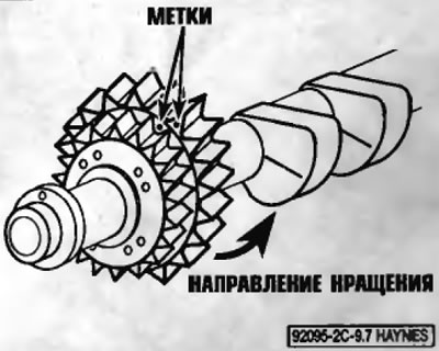
Pic. 9.7. Located on the alignment marks on the front and rear gears
8. Lubricate the shafts with clean engine oil, install them on the lower crankcase assembly and align the marks on the shafts (pic. 9.8).
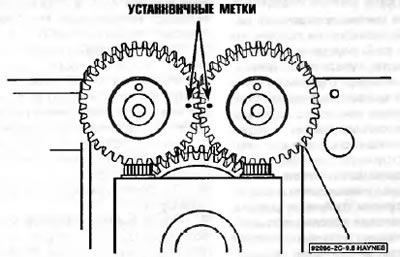
Pic. 9.8. Install the balance shafts so that the marks on the gear are aligned
9. Check the alignment of the neck No. 1 of the crankshaft. The crankshaft key must be located 180 from the balance shafts (pic. 9.9). Double check the position of the marks on the shafts.
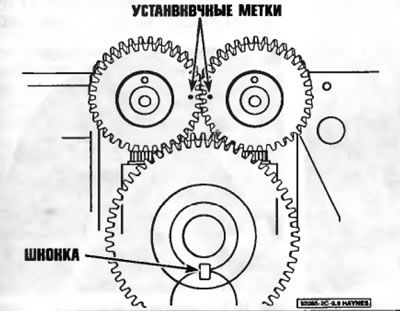
Pic. 9.9. Align the position of the alignment marks on the balance shafts when the crankshaft key is rotated 180°away from the balance shafts
10. Install the balance shaft housing and tighten the bolts to the prescribed torque specified in Specifications at the beginning of this chapter. Follow the correct bolt tightening sequence (pic. 9.10).
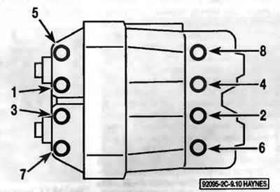
Pic. 9.10. Control Shaft Housing Bolt Tightening Sequence
11. Install the oil pump (see chapter 2A).
12. The rest of the installation is performed in the reverse order of removal.