Modulator
It consists of an electric pump and four solenoid valves. An electric pump pressurizes and fills the reservoirs in the modulator. The pump and reservoirs are located in the modulator block. Solenoid valves modulate the pressure in the wheel brake cylinders during ABS operation.
Speed sensors
located near each wheel. They generate impulses when the teeth of the rotors pass near them, and transmit them to the ABS electronic control device, on the basis of which the wheel speed is calculated.
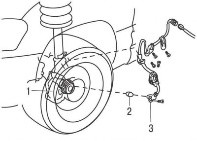
Pic. 11.3. Front speed sensor: 1 – a rotor of the gauge of frequency of rotation of a forward wheel; 2 - bushing; 3 - front wheel speed sensor
The front speed sensors are mounted on the steering knuckles in close proximity to the rotor, which is an integral part of the outer CV joint of the wheel drive shaft (pic. 11.3).
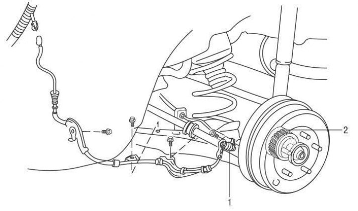
Pic. 11.4. Rear speed sensor on all models up to 2001 and on all-wheel drive models since 2001: 1 - rear wheel speed sensor; 2 – a rotor of the gauge of frequency of rotation of a back wheel
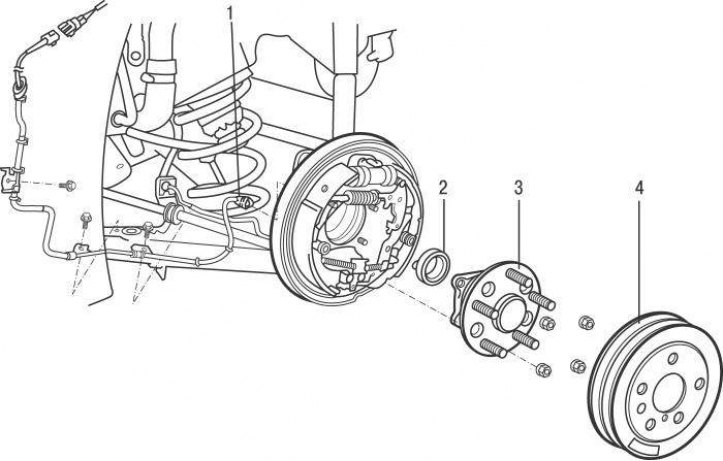
Pic. 11.5. Rear speed sensor on single drive axle models since 2001: 1 - electrical connector; 2 – the gauge of frequency of rotation of a back wheel; 3 - hub; 4 - brake drum
On all models up to 2001 and all-wheel drive models since 2001, the rear speed sensors are bolted to the rear suspension arms (pic. 11.4). On models with one drive axle from 2001 to the center of the rear hub (pic. 11.5).
Deceleration sensor
Installed on all-wheel drive models until 2001 and all models from 2001. The sensor is installed under the center console and sends negative acceleration signals to the ABS electronic control unit.
On models up to 2001, it is located under the instrument panel on the front passenger side, and on models since 2001, it is combined with the modulator unit. The function of the ECU is to receive and process information received from the wheel speed sensors and control the pressure in the pipeline in such a way as to prevent the wheels from locking. The electronic control unit also performs a diagnostic function, by illuminating a warning lamp, warning the driver about a malfunction in electrical circuits or ABS elements. The fault code is stored in the computer memory and can be read without the use of special tools.
Before triggering trouble codes, perform a few simple checks:
- check the brake fluid level in the compensation tank;
- check the connection of all electrical ABS connectors;
- check the integrity of the fuses.
The electronic control unit stores the fault code until its memory is cleared or the fault is corrected.
The ABS warning lamp should come on after the ignition is switched on and go out immediately after the engine is started. If the lamp continues to burn, the self-diagnosis system has registered a malfunction in the electrical circuits or elements of the anti-lock braking system.
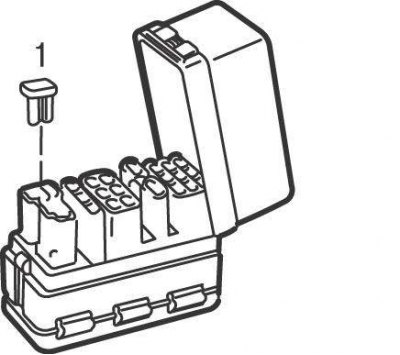
Pic. 11.6. Jumper location (1) in the diagnostic socket on models up to 2001
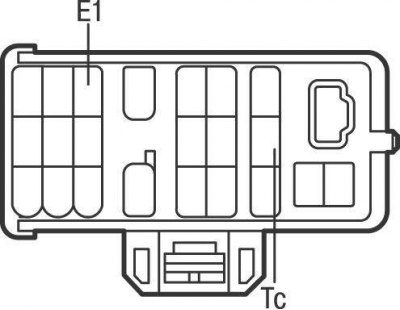
Pic. 11.7. Location of contacts Tc and E1 of the diagnostic socket on models up to 2001
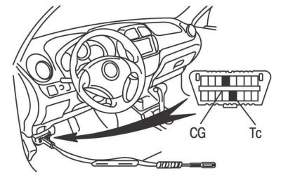
Pic. 11.8. Location of the diagnostic connector and pins E1 and CG on models from 2001
You can read diagnostic trouble codes as follows. Turn the ignition key to the OFF position (ignition off). On models prior to 2001, remove jumper 1 (pic. 11.6), then with an additional wire connect the contacts Tc and E1 of the diagnostic connector located near the power steering compensation tank (pic. 11.7). On models from 2001, connect pins E1 and CG of the diagnostic connector located on the left side under the instrument panel (pic. 11.8). Turn on the ignition without starting the engine and determine the fault code by the number of flashes of the ABS warning lamp.
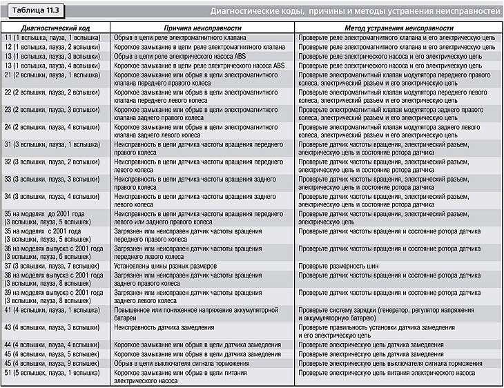
The diagnostic code number is determined by the number of flashes of the ABS warning lamp. If there is a malfunction, the ABS warning lamp flashes in two series, the interval between which is 1.5 s. For example, code 34 (Malfunction in a chain of the gauge of frequency of rotation of a back left wheel): The lamp flashes 3 times, pauses for 1.5 seconds, then the lamp flashes 4 more times. If several fault codes are stored in the memory, then there is a 2.5 s pause before the indication of each subsequent code. In the absence of malfunctions, the control lamp flashes every 0.5 s.
Diagnostic codes, causes and troubleshooting methods are given in Table. 11.3.
After reading the codes and troubleshooting, clear the ECU memory. On models before 2001, disconnect pins E1 and Tc of the diagnostic connector, and on models from 2001, disconnect pins E1 and CG. Turn on the ignition without starting the engine and clear the ECU memory by depressing the brake pedal 8 or more times within 3 seconds. On pre-2001 models, reinstall jumper 1 (pic. 11.6). Close the diagnostic socket cover.
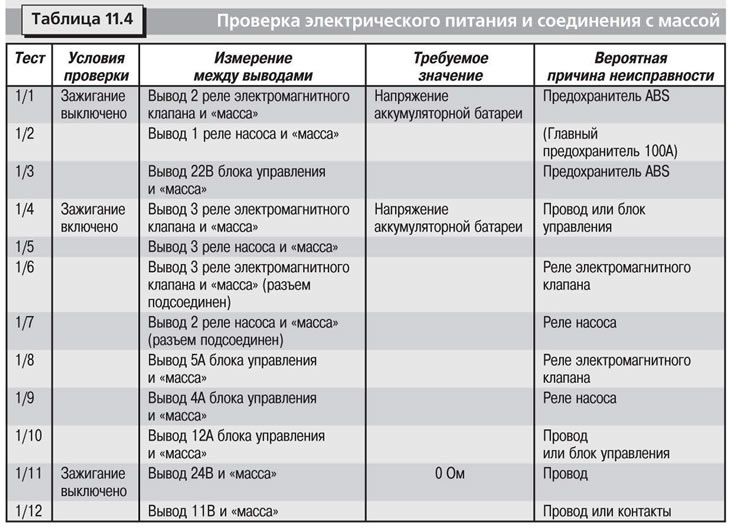
Checking the electrical supply and connection to «weight»
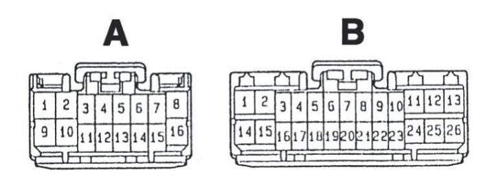
Pic. 11.9. Electrical connectors (A and B) double relay
All electrical power and connection checks «weight» carry out using a tester, connecting it to the contacts of the previously disconnected electrical connector of the dual relay (pic. 11.9).
Power supply and connection tests «weight» are given in table. 11.4.
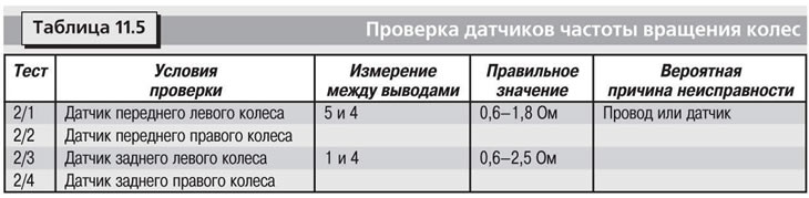
Checking wheel speed sensors
Check the wheel speed sensors with the electrical connectors disconnected from the control unit. The verification procedure is given in table. 11.5.