



Removal
Proceed with removal in the following order:
- turn off the ignition and disconnect the ground wire from the battery;
- apply the parking brake and block the rear wheels with chocks;
- loosen the right front wheel mounting nuts. Raise the front of the vehicle and support it on stands. Remove the right front wheel and the right front wheel arch mudguard;
- remove the power steering fluid reservoir together with the bracket. If the vehicle is equipped with an anti-lock brake system (ABS), remove the ABS unit together with the bracket;
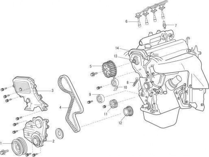
Figure 3.11. Timing drive: 1 – crankshaft pulley; 2 – lower toothed belt cover; 3 – upper toothed belt cover; 4 – toothed belt; 5 – toothed belt guide; 6 – high-voltage wires with spark plug tips; 7 – spark plug; 8 – spring; 9 – crankshaft timing belt pulley; 10 – oil pump pulley; 11 – idle roller; 12 – tension roller; 13 – camshaft timing belt pulley; 14 – protective box for wiring harness
- remove the high-voltage wire terminals by pulling upwards and turning them at the same time 6 (figure 3.11) with spark plugs;
- use a jet of compressed air to clean the spark plugs, which will prevent dirt from getting into the engine cylinder after removing the spark plugs. Remove the spark plugs;
- remove the poly V-belts of the accessory drive;
- remove the generator and generator bracket;
- separate the protective box 14 for the wiring harness from the front of the engine;
- using a jack and a wooden block, support the engine by the oil pan. Remove 3 bolts and right engine mount;
- unscrew the screws, disconnect the rods and wires and remove the upper cover of the 3 toothed belt and the gasket;
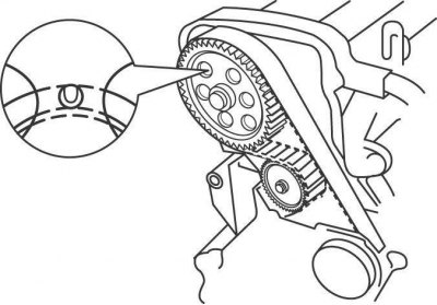
Figure 3.12. TDC mark on the cylinder head cover, visible through the small hole in the camshaft timing belt pulley
- set the piston of the first cylinder to TDC (in the compression stroke position). Check that the TDC mark on the cylinder head cover is visible through the small hole in the camshaft timing belt pulley (figure 3.12);
- use chalk, marker, or paint to mark the direction of rotation of the timing belt, and also make alignment marks on the camshaft pulley and timing belt. If the timing belt rotates in the opposite direction during installation, it will cause damage;
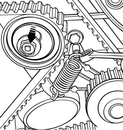
Figure 3.13. Location of the tension roller mounting bolt and spring removal
- loosen the tension roller mounting bolt and remove the spring (figure 3.13). Remove the timing belt from the pulleys. If it is necessary to remove the cylinder head, camshaft or replace the camshaft seal ring, it is not necessary to remove the timing belt from the crankshaft pulley;
The original is this website [toyotaman.ru]
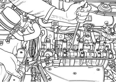
Figure 3.14. Using wrenches to hold the camshaft from turning and loosening the timing belt pulley mounting bolt
- if the camshaft timing belt pulley is worn or damaged, remove the cylinder head cover. Hold the camshaft with a wrench to prevent it from turning (figure 3.14) using the hex key, unscrew the mounting bolt and remove the timing belt pulley from the camshaft;
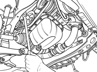
Figure 3.15. Using a screwdriver blade to prevent the flywheel from turning and unscrewing the crankshaft pulley mounting bolt
- remove the cover covering the flywheel inspection hole and use a large flat-head screwdriver blade to secure the flywheel ring gear from turning (figure 3.15). Remove the crankshaft pulley mounting bolt. Since the bolt is tight, use a wrench with a large leverage. Using a pry bar or vibration damper puller, remove the pulley from the crankshaft (figure 3.16). Before removing the pulley, make sure that the piston of the first cylinder is set to TDC;
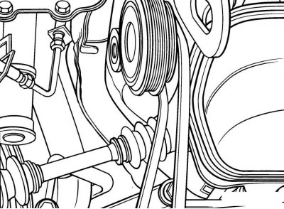
Figure 3.16. Using a pry bar to remove the pulley from the crankshaft
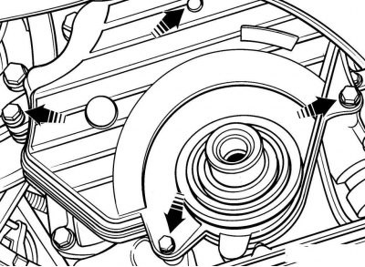
Figure 3.17. Location of the lower timing belt cover mounting bolts
- unscrew the bolts (figure 3.17) and remove the lower timing belt cover and its gasket. Remove the timing belt guide from the crankshaft;
- if the timing belt is to be reinstalled, make alignment marks on the crankshaft pulley and timing belt;
- slide the timing belt off the pulley and remove it from the engine;
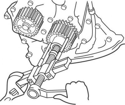
Figure 3.18. Using a puller to remove a pulley from a crankshaft
- if the pulley is worn or damaged or the front crankshaft seal needs to be replaced, remove the timing belt pulley from the crankshaft. The pulley should be easily removed from the crankshaft. If the pulley is very tight, remove it with a puller (figure 3.18). To attach the puller jaws, drill 2 holes in the pulley and cut threads in them.
Examination
Caution! Do not twist or bend the timing belt. Prevent the timing belt from coming into contact with oil, coolant or fuel.
Caution! Do not turn the engine crankshaft with the timing belt removed, as the pistons may hit the valves.
Check the condition and smooth rotation of the idler and tension rollers. Check the condition and measure the length of the spring, which for engines from 1996 to 1997 should be 46.0 mm, and for engines from 1998 to 2000 – 42.0 mm.
A broken timing belt on a running engine can cause the pistons to hit the valves, which can cause the valves to become warped. Check the valve clearances. On deformed valves they will be significantly larger than required.
If the timing belt teeth have chipped, the water pump, oil pump, or camshaft may be seized.
If the outer surface of the timing belt is significantly worn or delaminated, check the condition of the idler and tension roller races.
If wear or damage is found on only one side of the belt, check the timing belt guide and timing belt pulley alignment.
Attention! If there are any defects on the timing belt, be sure to replace it.
Note: Professionals recommend replacing the timing belt whenever it is removed, as a belt failure while the engine is running can cause serious engine damage and costly repairs.
Installation
Perform installation in the following order:
- wipe away all dirt and grease from the front of the engine, in the area where the timing belt runs;
- if removed, reinstall the idler and tension rollers and tension roller spring. Move the tension roller to maximum spring tension and temporarily secure it in this position with a bolt;
- install the timing belt pulleys onto the camshaft and crankshaft. Install the crankshaft pulley so that the crankshaft sensor teeth are located on the side of the front engine cover;
- check that the TDC mark on the cylinder head cover is visible through the small hole in the camshaft timing belt pulley (see Figure 3.12), and the crankshaft pulley key is directed towards the TDC mark on the front cover. In this case, the piston of the first cylinder is at TDC in the compression stroke;
- install the timing belt on the crankshaft pulleys, oil pump pulley, water pump pulley, and idler and tensioner pulleys. When reinstalling the timing belt, align the marks previously made;
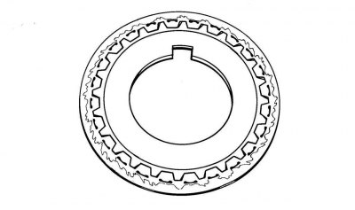
Figure 3.19. The side of the timing belt guide that should be located on the belt side
- install the timing belt guide onto the crankshaft, with the side with the tooth pattern facing the timing belt (figure 3.19);
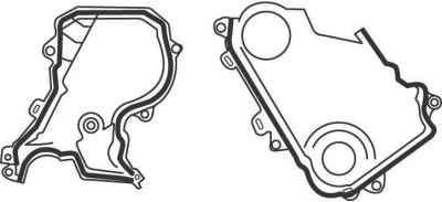
Figure 3.21. Places where a layer of sealant is applied to the upper and lower toothed belt casing
- apply a layer of sealant to the mating surface (see figure 3.21), install the lower timing belt cover and secure it with bolts;
- install the crankshaft pulley and check that the mark on the pulley is aligned with the TDC mark on the front cover. Screw in and tighten the pulley mounting bolt to a torque of 108 N·m;
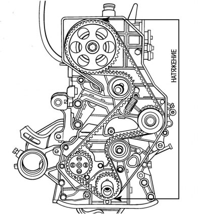
Figure 3.20. The branch tensioned when installing the toothed belt on the camshaft pulley
- install the timing belt on the camshaft pulley, while tensioning the belt branch located on the front side of the engine (figure 3.20);
- loosen the tension roller mounting bolt in the retracted position, this will cause the spring to rotate the roller, resulting in tension on the belt;
- crankshaft pulley mounting bolt, slowly turn the crankshaft clockwise 1 7/8 turns until the mark on the crankshaft pulley aligns with the 45° BTDC mark located on the lower timing belt cover, then tighten the tension roller mounting bolt to a torque of 42 N·m;
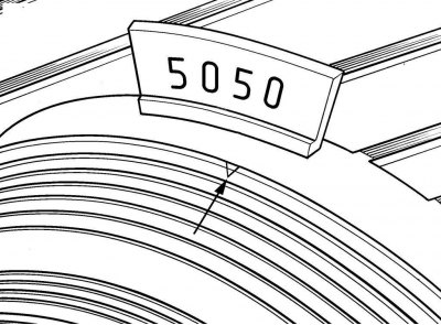
Figure 3.1. Aligning the mark on the vibration damper with the TDC mark on the front cover
- using the crankshaft pulley mounting bolt, turn the crankshaft clockwise 2 1/8 turns until the mark on the vibration damper aligns with the TDC mark on the front cover (see Figure 3.1). Check that the TDC mark on the cylinder head cover is visible through the small hole in the camshaft timing belt pulley, otherwise repeat the timing belt installation operations (see Figure 3.12).
Caution! Do not start the engine until you are absolutely sure that the timing belt is installed correctly. If the belt is installed incorrectly, serious and costly engine damage can occur.
Further installation is carried out in the reverse order of removal, taking into account the following.
Apply a layer of sealant to the mating surface, install the upper timing belt cover and secure it with screws (figure 3.21).