



Removal
Attention! Accurate adherence to valve timing is very important, but for DOHC engines it is extremely important. Incorrect installation of the phases can seriously damage the engine. Be careful when installing the timing belt and before the first start after repair, check the coincidence of the marks again.
Timing drive assembly
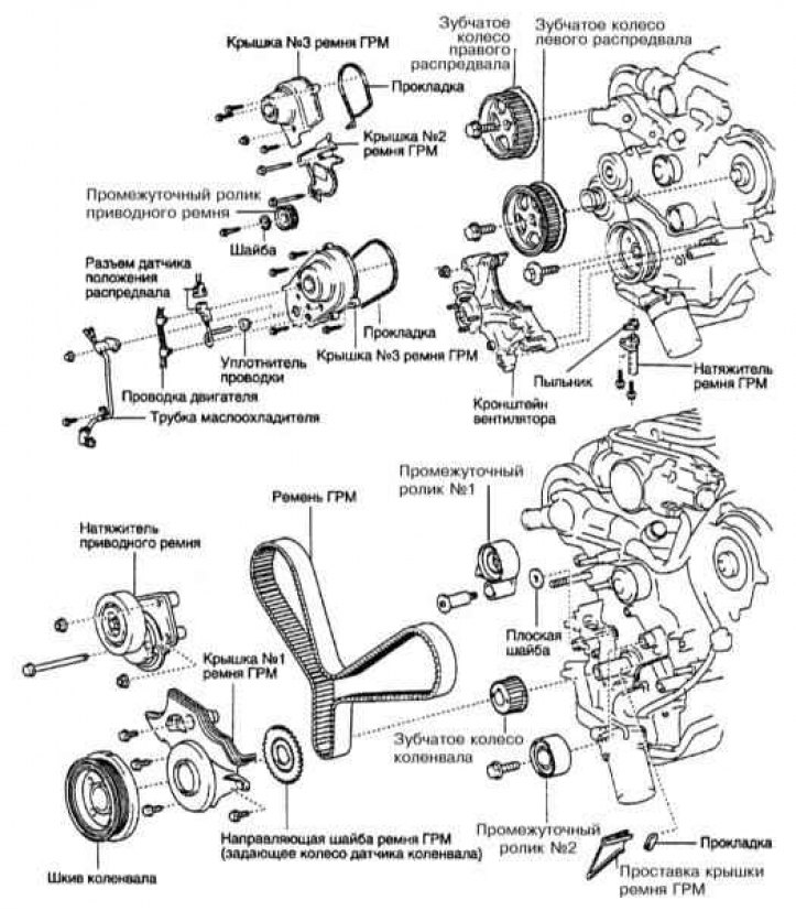
1. Disconnect the negative cable from the battery.
Warning! If the car stereo system is equipped with a security code, make sure you have the correct combination to activate the audio system before disconnecting the battery!
2. Remove the crankcase guard.
3. Drain the coolant from the radiator and engine block (see chapter Engine cooling, interior heating and air conditioning systems).
4. Remove the radiator (see chapter Engine cooling, interior heating and air conditioning systems).
5. Remove the throttle body cover.
6. Remove the air intake duct.
7. Remove the drive belt with clutch and crankshaft pulley.
8. Without disconnecting the hydraulic pipes, remove the power steering pump, move it to the side and tie it up so that it does not interfere.
9. After unscrewing the bolt, then removing the cover, remove the drive belt idler roller (refer to the illustration above).
10. Remove the right cover (right No.3) of the timing belt.
11. Remove the left timing belt cover (left #3). Be careful when disconnecting the camshaft position (CMP) sensor wiring.
12. Remove the next timing belt cover (cover #2).
13. Without disconnecting the air conditioning pipes, remove the air conditioning compressor, move it to the side and tie it up there so that it doesn't get in the way.
14. Remove the fan bracket. It uses bolts of different sizes to secure it - stack them so that they do not get mixed up during installation.
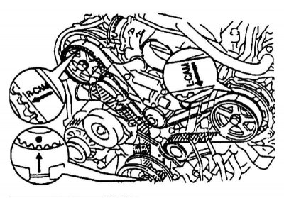
15. If the timing belt is to be reinstalled, locate the three timing marks on it by rotating the crankshaft clockwise. Locate the marks on the crankshaft and camshaft gears. If the marks on the belt are worn, apply new ones to facilitate installation (refer to the accompanying illustration).
16. Loosen, but do not remove, the crankshaft pulley mounting bolt. You will need a special tool to hold the crankshaft from turning.
17. Set the piston of cylinder No.1 to TDC of the compression stroke.
- Turn the crankshaft pulley so that its mark aligns with the mark on the timing belt cover No.1.
- Check that the marks on the camshaft gears match the marks on the rear timing belt covers. If the marks do not match, the piston of cylinder No.1 is not set at TDC of the compression stroke. Turn the crankshaft exactly one revolution until the next alignment of the pulley mark with mark 0 on cover No.1 of the timing belt.
- Loosen the crankshaft pulley bolt, being careful not to disturb the marks. Do not rotate the crankshaft pulley.
18. Remove the timing belt tensioner and boot by unscrewing the two bolts. If you are replacing only the belt tensioner, secure the belt to the pulley with wire. Mark the belt and the right camshaft gear.
19. Remove the belt from the camshaft sprockets. To do this, loosen the belt tension between the camshaft sprockets by placing a spanner on the left camshaft sprocket mounting bolt and turning it slightly clockwise.
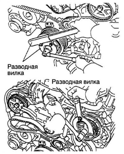
20. To remove the camshaft gears, use a fork tool to secure the gear from turning and unscrew the central bolt (refer to the accompanying illustration). Try not to turn the gears.
21. Remove the generator.
22. Remove the drive belt tensioner.
23. To remove the crankshaft pulley, the central bolt must already be unscrewed. Pull the pulley off the crankshaft nose using a suitable puller. Do not turn the crankshaft to avoid disturbing the TDC setting.
24. Remove the lower timing belt cover (cover No.1).
25. Remove the guide washer and cover spacer.
26. Remove the timing belt from the engine. If the belt is to be reinstalled and the timing marks on it have worn off, apply new ones relative to the dot mark on the crankshaft gear.
27. If necessary, remove the intermediate rollers and check that they rotate smoothly.
28. If it is necessary to remove the crankshaft gear, pull it off with a suitable puller. Try not to move the crankshaft from TDC.
Examination
1. Check the condition of the timing belt. Do not bend it at an acute angle or turn it inside out. Do not allow oil, water, antifreeze or solvents to come into contact with the belt. If the belt teeth are damaged, check that the camshafts are not blocked. If there is noticeable wear or cracks on the back surface of the belt, check the surface of the rollers and the water pump pulley for damage. If one-sided belt wear is detected, check the parallelism of the pulleys and their axes, guide washer. If there is noticeable wear on the belt teeth, the belt covers or gear teeth may be damaged. Do not use the timing belt tension to loosen the camshaft gear mounting bolts.
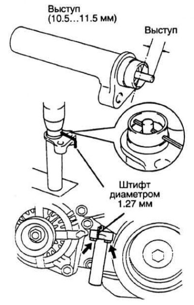
2. Check the condition of the intermediate rollers. Check the integrity of their bearing seals. Replace the rollers if necessary. Check for leaks in the tensioner. Try to push the rod in – it should not move. If you can push the rod in, replace the tensioner. Measure the rod protrusion – it should be 10.5–11.5 mm (refer to the accompanying illustration).
3. Check for leaks in the water pump. The pump should rotate smoothly, without any play.
Installation
1. If removed, install the crankshaft gear by aligning the key on it with the groove. It may be necessary to carefully press the gear onto the shaft using a suitable piece of pipe.
2. Install the intermediate rollers. Apply a few drops of Loctite 242 or similar to the bolt threads. Tighten the bolts to 35 Nm. Check that the rollers rotate smoothly.
3. Temporarily install the timing belt. Thoroughly clean the toothed wheels and rollers from oil and water, wipe them with a clean dry cloth. Do not use solvents. Align the timing mark on the belt with the mark on the crankshaft toothed wheel. Put the belt on the crankshaft toothed wheel and the idler pulleys.
4. Install the timing belt cover spacer.
5. Install the guide washer with the convex side facing out.
6. Install the timing belt cover and secure it with four bolts.
7. Install the crankshaft pulley. Align the key with the slot and install the pulley. To do this, you may have to press the pulley on with a piece of suitable pipe.
8. Install the drive belt tensioner (not timing belt). Tighten the 106 mm long bolt and nuts to 16 Nm.
9. Install the generator.
10. Check the position of the crankshaft pulley. The mark on the pulley should align with the 0 mark on the timing belt cover.
11. Install the camshaft gears. Put the gears on, aligning their holes with the camshaft pins. Hold the gears from turning with a fork tool and tighten their mounting bolts to 108 Nm. Clean the gears thoroughly and wipe them dry with a clean rag. Do not use solvents.
12. Install the belt on the camshaft sprockets:
- Turn the left camshaft gear until its timing mark aligns with the timing mark on the timing belt. Put the belt on the gear.
- Turn the left camshaft timing gear counterclockwise to apply tension to the belt on the shoulder between the left camshaft timing gear and the crankshaft.
- Turn the right camshaft gear until the timing mark on the belt aligns with the timing mark on the gear. Put the belt on the gear.
13. Using a press, press in the tensioner rod. This will require a force of about 981-987 N. Align the holes in the rod and the tensioner body and insert a 1.27 mm pin to secure the rod. Release the press and put on the boot. Install the tensioner on the engine and tighten its mounting bolts alternately to a torque of 26 Nm. After installing the tensioner, remove the pin with pliers.
14. Check the timing marks. Temporarily install the crankshaft pulley mounting bolt. Slowly turn the crankshaft clockwise two full turns. Check the alignment of the timing marks on the gears and pulley.
15. If the timing marks match, tighten the pulley mounting bolt to 245 Nm. A fork tool will be required to prevent the pulley from turning.
16. Install the fan bracket. Install the bracket mounting bolts in their places. The bolts are tightened as follows:
- Tighten bolts with 12 mm heads to 16 Nm.
- Tighten bolts with 14 mm heads to a torque of 32 Nm.
17. Install the air conditioning compressor (with appropriate equipment).
18. Install timing belt cover No.2 and tighten the two mounting bolts to 16 Nm.
19. Install the right timing belt cover. Tighten the bolts and nut to 7.5 Nm.
20. Install the left timing belt cover:
- Install the oil cooler pipe, securing it with a nut and bolt.
- Route the CMP sensor wiring through the hole in the cover.
- Install the timing belt cover, aligning it with the fan bracket.
- Tighten the bolt and nut to 7.5 Nm.
- Install the sensor wiring seal into the cover, connect the connector and attach it to the bracket.
- Secure the engine wiring.
21. Install the drive belt idler roller and tighten its bolt to 39 Nm.
22. Install the power steering pump and tighten the bolts to 17 Nm.
23. Install the remaining components in the reverse order of their removal.
24. Start the engine and check for leaks and extraneous noise.