
Removing
Note. When removing and installing camshafts, it is necessary to use 2 additional technological bolts M6x1 16–20 mm long
Removal in the following order:
- remove the cylinder head cover;
- remove the ignition distributor;
- remove the toothed belt, camshaft pulley and rear toothed belt cover;
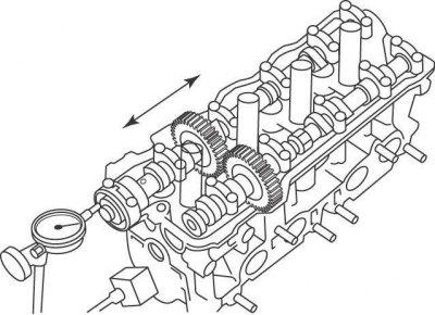
Pic. 3.25. Installation of a dial indicator for measuring the axial clearance of the camshaft
- check the camshaft end play. Install a bracket with a dial indicator on the engine block so that the measuring tip of the indicator rests on the end of the camshaft (pic. 3.25);
- move the camshaft along the axis to one side until it stops and set the indicator to 0. Move the camshaft along the axis to the other side until it stops and fix the value on the indicator. If the gap exceeds the allowable value, it is necessary to replace the camshaft and / or the cylinder head;
Exhaust camshaft
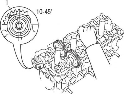
Pic. 3.26. The position of the intake camshaft to the position where the dowel pin (1) located to the left at an angle of 10–45°from the vertical axis
- turn the intake camshaft so that dowel pin 1 (pic. 3.26) was located to the left at an angle of 10–45°from the vertical axis. In this case, the exhaust camshaft will rotate to a position in which the pressure of the valve springs on all camshaft cams will be uniform;
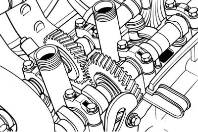
Pic. 3.27. Bolt location of the auxiliary gear of the exhaust camshaft to the main gear
- with an additional technological bolt M6x1, attach the auxiliary gear of the exhaust camshaft to the main gear (pic. 3.27);
- unscrew 2 bolts and remove the rear cover of the camshaft bearing;
- in turn, turning 1/4 turn, loosen, then completely unscrew the bolts for fastening covers 1, 2 and 4 for fastening the camshaft bearings. Remove 1, 2 and 4 camshaft bearing caps;
- in turn, turning 1/4 turn, loosen, then completely unscrew the bolts securing the cover 3 of the camshaft bearing. Remove cover 3 of the camshaft bearing;
- remove the camshaft;
- to remove the gear from the exhaust camshaft, secure the camshaft to the hexagon in a vice with soft jaws;
- install the second additional bolt M6x1 in the technological hole of the auxiliary gear of the camshaft. With a screwdriver inserted between the camshaft and the second auxiliary bolt, turn the auxiliary gear clockwise and remove the first auxiliary bolt;
- remove the auxiliary gear circlip;
- remove the spring washer, auxiliary gear and camshaft gear snap ring.
Attention! When loosening and turning out the bolts of the camshaft bearing caps, make sure that the camshaft is evenly, without distortion, separated from the cylinder head. Otherwise, reinstall the bearing caps and rotate the intake camshaft so that the dowel pin is on the left at an angle of 10-45°from the vertical axis (see fig. 3.26).
Inlet camshaft
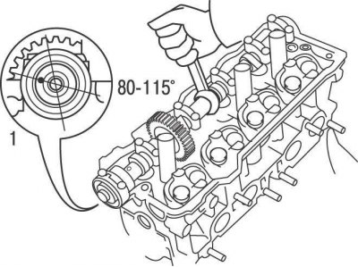
Pic. 3.28. The position of the intake camshaft to the position where the dowel pin (1) located to the left at an angle of 80–115°from the vertical axis
- turn the intake camshaft so that dowel pin 1 (pic. 3.28) located to the left at an angle of 80–115°from the vertical axis;
- turn out bolts and remove a forward cover of bearings of a camshaft of inlet valves and a sealing ring;
- in turn, turning 1/4 turn, loosen, then completely unscrew the bolts for fastening covers 1, 3 and 4 for fastening the camshaft bearings. Remove 1, 3 and 4 camshaft bearing caps;
- in turn, turning 1/4 turn, loosen, then completely unscrew the bolts securing the cover 2 of the camshaft bearing. Remove cover 2 of the camshaft bearing;
- remove the camshaft.
Examination
Check in the following order:
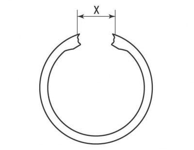
Pic. 3.29. Place for measuring the distance between the ends of the camshaft gear spring: X = 22.5–22.9 mm
1) measure the distance between the ends of the camshaft gear spring, which should be 22.5-22.9 mm (pic. 3.29). Otherwise, replace the spring;
Attention! Do not remove the cover using the levers. If the cover does not come off, leave it in place.
2) wipe off oil and mark the shims and pushers, remove them from the cylinder head with a magnetized tool and position them so that they are in place during installation;
3) check each pusher for wear and tear;
4) measure the outer diameter of each pusher and the corresponding pusher sockets. To determine the clearance, subtract the tappet diameter from the socket diameter. The nominal value of the pusher gap is 0.024–0.052 mm, the maximum allowable value is 0.07 mm. If the gap exceeds the maximum allowable value, replace the pushers;
5) visually examine the cams and bearing journals of the camshafts for the absence of wear, traces of corrosion, metal enveloping and the presence of tint colors, indicating local overheating;
6) Use a micrometer to measure the height of the camshaft cam. The nominal height of the intake camshaft cams is 42.01–42.11 mm, the maximum allowable value is 41.9 mm. The nominal value of the height of the camshaft cams of the exhaust valves is 40.06–40.16 mm, the maximum permissible value is 39.95 mm. If the cam height is less than the limit, replace the camshaft.
7) Use a micrometer to measure the diameter of each camshaft bearing journal. Necks are measured at several points, both in diameter and in length, this will reveal ovality and taper, if any. The nominal value of the diameter of the camshaft bearing journals is 26.959–26.975 mm. If the diameter of any neck is less than the nominal value, replace the camshaft;
8) check the clearances in the camshaft bearings as follows;
9) the method of verification is to use a product known as Plastigage. This is a round calibrated plastic rod that is compressed between the bearing cap and the camshaft journal. After removing the bearing cover, the deformed plastic rod is measured with a special gauge, which is included in the Plastigage kit.
10) The procedure for using Plastigage is as follows:
- clean the camshaft journals, bearing caps and camshaft mounting locations in the cylinder head;
- install the camshafts in the cylinder head without lubrication and pushers;
- cut off a few pieces of plastic Plastigage rod (they should be slightly shorter than the width of the bearings) and install them on each camshaft journal;
- install the bearing caps, the identification arrows of which should be directed towards the toothed belt and tighten the fastening bolts to the required torque. Tighten the bolts in turn, sequentially turning each bolt 1/4 turn;
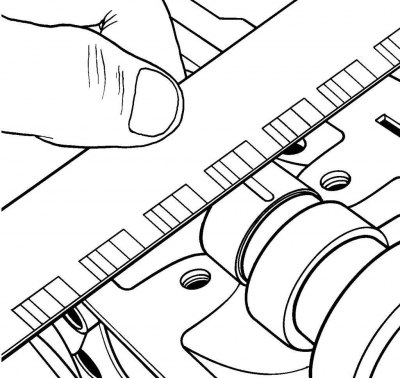
Pic. 3.30. Measuring the width of a deformed Plastigage bar using a scale bar
- Turn out bolts and remove covers of bearings of camshafts. Attach the scale printed on the package to the deformed plastic rod. Comparing the width of the deformed plastic rod with the reference width on the scale bar, determine the amount of gap (pic. 3.30). If the clearance is greater than the limit, replace the camshaft and/or cylinder head;
- Finally, carefully clean any traces of Plastigage from bearing caps and camshafts
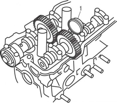
Pic. 3.31. Using the Dial Indicator (1) for measuring backlash in gearing of camshaft gears
11) measure the backlash in the gearing of the camshaft gears. Install the camshafts without installing tappets and auxiliary gear. Install the bracket with dial gauge 1 on the cylinder head (pic. 3.31) so that the measuring tip of the indicator rests on one of the teeth of the camshaft gear.
Attention! Do not rotate the camshafts while measuring the clearance using the Plastigage method.
Turn the camshaft gear to one side until it stops against the teeth of the second gear and set the indicator to 0. Turn the gear to the other side within the play and fix the value on the indicator. If the backlash exceeds the allowable value, the camshafts must be replaced.
Installation
Inlet camshaft
Install in the following order:
- lubricate the pushers with engine oil and install them in the places in which they were before removal. Make sure that the shims are installed on the pushrods;
- lubricate the necks and camshaft cams with engine oil;
- install the intake camshaft so that the locating pin is located on the left at an angle of 80°from the vertical axis (see fig. 3.28);
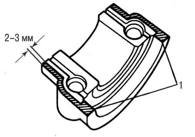
Pic. 3.32. Sealing locations (1) on the mating surface of the front cover of the camshaft bearing
- apply a thin coat of RTV 1 sealant (pic. 3.32) 2-3 mm wide on the outer edges of the mating surface of the front camshaft bearing cover and install the cover immediately;
- install the remaining camshaft bearing caps in accordance with their numbering, while the arrows printed on the caps should be directed towards the toothed belt;
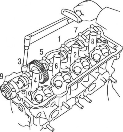
Pic. 3.33. The sequence of tightening the bolts of the bearing caps of the intake camshaft
- in the sequence shown in Figure 3.33, turning 1/4 turn in one pass, screw in the cover fastening bolts and tighten them with a torque of 19 Nm;
- Lubricate the outer surface and the working edge of the new camshaft sealing ring with engine oihp a tubular mandrel, with an outer diameter slightly smaller than the outer diameter of the ring, install the sealing ring in place.
Exhaust camshaft
Install in the following order:
- reinstall the auxiliary gear to the exhaust camshaft. Install the spring, auxiliary gear, spring washer and secure them with a circlip;
- install the first additional M6x1 bolt into the access hole of the auxiliary camshaft gear. Using a screwdriver inserted between the camshaft and the first sub-bolt, turn the sub-gear clockwise and screw in and tighten the second sub-bolt to press the sub-gear against the camshaft gear. Remove the first auxiliary bolt;
- lubricate the pushers with engine oil and install them in the places in which they were before removal. Make sure that the shims are installed on the pushrods;
- lubricate the necks and camshaft cams with engine oil;
- install the intake camshaft over the cylinder head so that the dowel pin is on the left at an angle of 10°from the vertical axis (see fig. 3.26);
- Align the timing marks on the gears of the intake and exhaust camshafts and install the exhaust camshaft into the cylinder head. To facilitate installation, turn the camshaft slightly to one side or the other;
- install the camshaft bearing caps in accordance with their numbering, while the arrows on the caps should be directed towards the toothed belt;
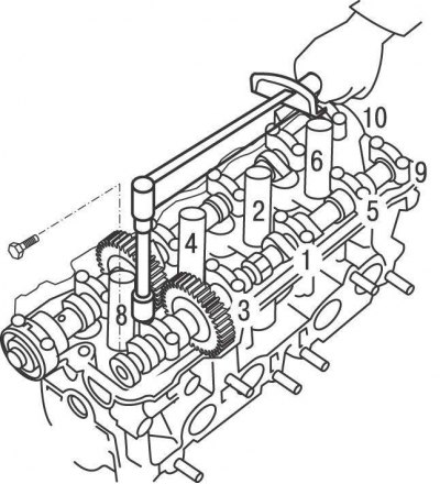
Pic. 3.34. The sequence of tightening the bolts of the bearing caps of the exhaust camshaft
- in the sequence shown in Figure 3.34, turning 1/4 turn in one pass, screw in the cover fastening bolts and tighten them with a torque of 19 Nm;
- unscrew the additional bolt that compresses the gears of the exhaust camshaft;
- install semicircular plugs in the cylinder head;
- install the rear toothed belt cover;
- Align the dowel pin with the notch and install the timing belt pulley on the camshaft and secure with the bolt to 54 Nm. When tightening the pulley mounting bolt with a second wrench mounted on a hexagon, keep the camshaft from turning;
- install the toothed belt.
Further installation is carried out in the reverse order of removal.