
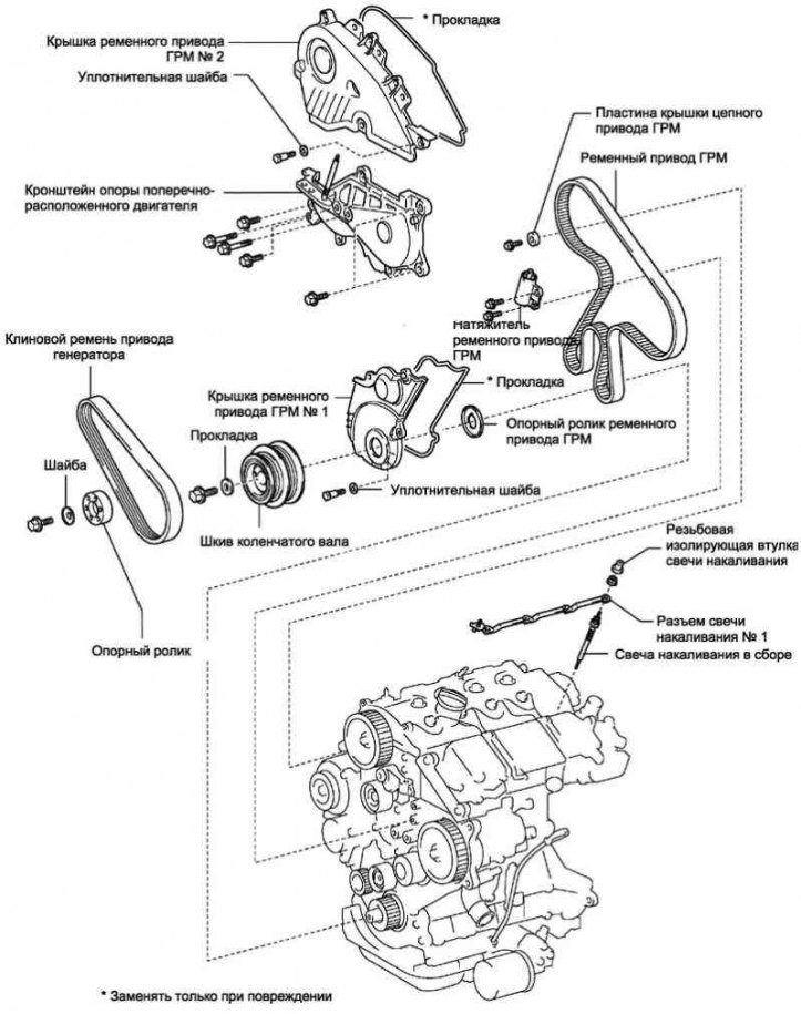
Pic. 2.337. Timing Belt Components
Disconnect the negative battery terminal.
Remove the front right wheel.
Remove the #1 engine bottom shield.
Remove the lower right engine cover.
Remove the top radiator shroud.
Remove the #1 engine cover.
Remove the injector drive electronics.
Remove V-belt No. 1 (air conditioning compressor drive from the crankshaft pulley).
Remove the alternator drive V-belt.
Removing the Power Steering Pump Support Roller Bracket
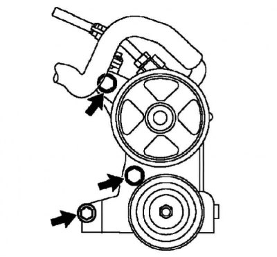
Pic. 2.338. Bolts of fastening of an arm of a basic roller of the pump of the hydraulic booster of a steering
Remove the 3 bolts and remove the power steering pump support roller bracket (pic. 2.338).
Note. Do not remove the hoses, but fix them on the body.
Removal of a pillow of the right support of the engine
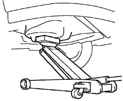
Pic. 2.339. Jack installation
Place a jack under the engine with a wooden block (pic. 2.339).
Remove the bolt, then disconnect the fuel return line.
Turn out 3 bolts and turn away 3 nuts, then remove a pillow of the right support of the engine.
Removing the crankshaft pulley
Using SST, remove the pulley mounting bolt.
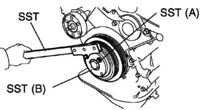
Pic. 2.340. Installing a special tool
Note. When using SST (A) (09213-70020) between SSTs (A) and SST (B) insert a flat washer (5 mm) (pic. 2.340).
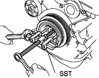
Pic. 2.341. Removing the crankshaft pulley
Remove pulley with SST (pic. 2.341).
Removing the support roller assembly
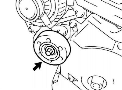
Pic. 2.342. Support roller pulley bolt
Loosen the bolt and remove the washer, then remove the pulley (pic. 2.342).
Disconnecting the engine wiring harness
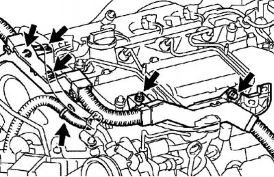
Pic. 2.343. Engine wiring harness attachment
Remove the 2 bolts and nut, then disconnect the 3 wire harness clips (pic. 2.343).
Removing cover No. 2 of the timing belt drive
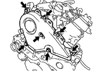
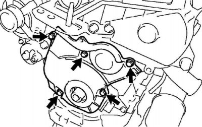
Pic. 2.344. Fastening cover No. 2 timing belt drive
Remove 7 bolts, remove 7 sealing washers, then remove the timing belt cover (pic. 2.344).
Removing cover No. 1 of the timing belt drive
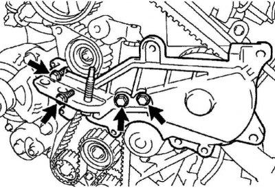
Pic. 2.345. Engine wiring harness attachment
Remove the 5 bolts, remove the 5 seal washers, then remove the timing belt cover (pic. 2.345).
Remove the timing belt drive roller.
Removing the transverse engine support bracket
Pic. 2.346. Fastening of an arm of a support of the transversely located engine
Remove 4 bolts and remove engine mount bracket (pic. 2.346).
Installing the piston of cylinder No. 1 at TDC of the compression stroke
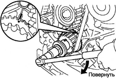
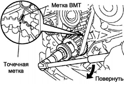
Pic. 2.347. Alignment of the mark on the timing gear with the TDC mark of the oil pump
Turn the crankshaft by the crankshaft pulley bolt and align the mark on the timing gear with the TDC mark on the oil pump (pic. 2.347).
Pic. 2.348. Alignment of the mark on the camshaft drive pulley with the parting line of the cylinder head and cylinder head cover
Make sure the timing mark on the camshaft drive pulley is aligned with the split line of the cylinder head and cylinder head cover (pic. 2.348).
Removing the timing chain cover plate
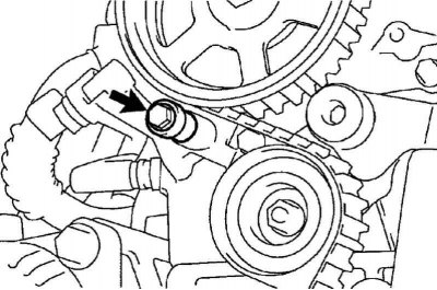
Pic. 2.349. Bolt of fastening of a plate of a cover of a timing chain drive
Unscrew the bolt and remove the timing chain cover plate (pic. 2.349).
Removing the timing belt drive
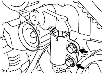
Pic. 2.351. Timing belt tensioner mounting bolts
Gradually, alternately loosen the 2 bolts to remove the timing belt tensioner (pic. 2.351).
Remove the timing belt drive.
Pic. 2.350. Timing Belt Tags
Note. If the timing belt drive is to be reused, before removing it, put an arrow on the belt indicating the direction of rotation of the engine crankshaft, and put alignment marks on the pulleys and on the belt. This will help when reinstalling the timing belt drive (pic. 2.350).
Installing the piston of cylinder No. 1 at TDC of the compression stroke
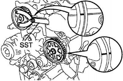
Pic. 2.352. The alignment of the pulley marks with the timing mark on the cylinder head and on the coolant pump
Using SST, install the crankshaft and injection pump pulleys so that the pulley marks are aligned with the timing mark on the cylinder head and on the coolant pump (pic. 2.352).
Turn the crankshaft by the crankshaft pulley bolt, and align the mark on the timing gear with the TDC mark on the oil pump (pic. 2.347).
Note. When rotating the camshaft and crankshaft, be careful, as the valve plates may come into contact with the piston crowns. As a result of contact, the valve plates may bend.
Timing belt drive installation
Remove oil and water from the pulleys, then clean the pulleys.
Note. Work on a cold engine.
Note. The use of chemical cleaning agents is prohibited.
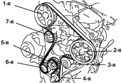
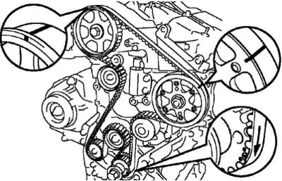
Pic. 2.353. Timing Belt Drive Component Installation Procedure: 1 - camshaft drive gear; 2 – a leading gear wheel of the fuel pump; 3 – a pulley of the pump of a cooling liquid; 4 - timing gear (crankshaft gear); 5 - support roller No. 2; 6 - oil pump drive gear; 7 - support roller No. 1
Install the timing belt drive in the following order shown in Figure 2.353.
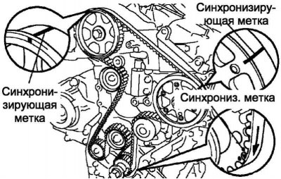
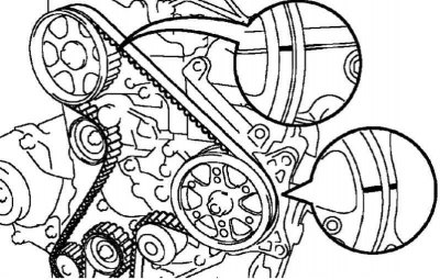
Pic. 2.354. Matching sync marks
Make sure that the sync marks are aligned, as shown in Figure 2.354.
Install the belt drive tensioner.
Using a press, carefully press the tensioner rod with a force of 981–9807 N.
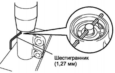
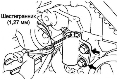
Pic. 2.355. Fixing the tensioner rod in the installation position with a hexagon
Align the holes in the stem and body, then insert a hex wrench into the holes (1.27 mm), to fix the tensioner rod in the installation position (pic. 2.355).
Remove the tensioner from under the press.
Install the tensioner by tightening the bolt (A) mounts.
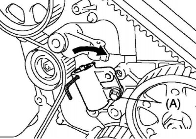
Pic. 2.356. Turning the tensioner before installing the second mounting bolt
Turn the tensioner clockwise, then install the second mounting bolt (pic. 2.356).
Tighten the 2 bolts gradually alternately.
Tightening torque: 21 Nm.
Pic. 2.357. Removing the hex
Remove the hexagon from the tensioner (pic. 2.357).
Checking the valve timing
Pic. 2.358. Turning the crankshaft 2 full turns
Slowly turn the crankshaft 2 full turns (720°) from TDC to TDC (pic. 2.358).
Note. Rotate the crankshaft only clockwise.
Attention! Align the TDC mark with the dot mark.
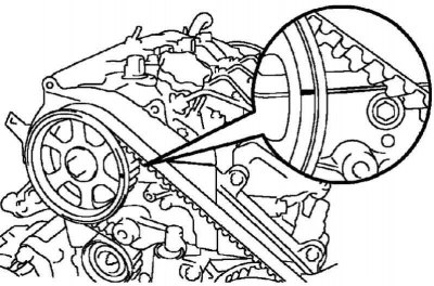
Pic. 2.359. Alignment of the timing marks on the pulleys with the marks on the engine
Make sure that the timing marks on the pulleys are aligned with the marks on the engine, as shown in Figure 2.359.
If the marks do not line up, remove the timing belt drive and reinstall it.
Turn out a bolt of fastening of a pulley of a cranked shaft.
Install the timing chain cover plate.
Tightening torque: 9.0 Nm.
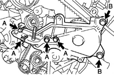
Pic. 2.360. The procedure for loosening and tightening the bolts of the transverse engine support bracket
Install the transverse motor support bracket and loosely tighten the 6 bolts (pic. 2.360).
Tighten the 4 bolts A to the prescribed torque.
Tightening torque: 37 Nm for bolt A.
Remove 2 screws B.
Installing the Timing Belt Drive Roller
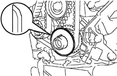
Pic. 2.361. Installation diagram of the belt drive support roller
Install the belt drive cam roller with the cover facing out (pic. 2.361).
Installing cover No. 1 timing belt drive
Check that the timing belt cover gasket is not cracked, deformed, etc.
If the gasket is cracked or deformed, replace it by following the steps below.
Using a screwdriver and scraper, remove the remnants of the old gasket.
Thoroughly clean all parts from sealant residues.
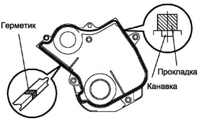
Pic. 2.362. Scheme of installing a new gasket on cover No. 1 of the timing belt drive
Remove the protective paper from the new gasket, then fix the gasket on the timing belt cover, as shown in Figure 2.362.
Note. Align the gasket in the groove.
At the corners, the thickness of the gasket should not decrease.
Then, firmly press the gasket so that it is firmly glued to the timing belt cover.
If there is a gap between the ends of the gasket, fill it with sealant.
Install the timing belt cover with gasket with 5 bolts and 5 sealing washers.
Tightening torque: 7.4 Nm.
After installing the timing belt cover, make sure that the gasket is not skewed or squeezed out from under the cover.
Installing cover No. 2 of the timing belt drive
Check that the timing belt cover gasket is not cracked, deformed, etc.
If the gasket is cracked or deformed, replace it by following the steps below.
Using a screwdriver and scraper, remove the remnants of the old gasket.
Thoroughly clean all parts from sealant residues.
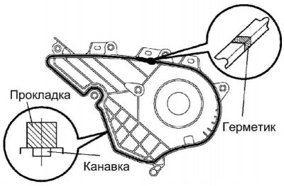
Pic. 2.363. Scheme of installing a new gasket on cover No. 1 of the timing belt drive
Remove the protective paper from the new gasket, then fix the gasket on the timing belt cover, as shown in Figure 2.363.
Note. Align the gasket in the groove.
Note. At the corners, the thickness of the gasket should not decrease.
Then, firmly press the gasket so that it is firmly glued to the timing belt cover.
If there is a gap between the ends of the gasket, fill it with sealant.
Install the timing belt cover with gasket with 7 bolts and 7 sealing washers.
Tightening torque: 7.4 Nm.
After installing the timing belt cover, make sure that the gasket is not skewed or squeezed out from under the cover.
Note. Install other components in the reverse order of removal.