



Caution! Dust generated during machine operation may contain asbestos, which is hazardous to health. Do not use compressed air to blow it out or inhale it. Wear a respirator when working on brakes. Do not clean mechanisms with petroleum-based solvents – there are special liquids for this purpose.
Warning. Brake pads are always replaced as a set on one axle - never replace pads on just one wheel.
1. Remove the brake disc (see paragraph 5).
2. Check the thickness of the brake pad friction linings. If the linings are worn to a thickness of 2 mm or less, the parking brake shoes must be replaced.
3. Remove the hub assembly (see chapter 10).
Note: The procedure for removing and installing the brake pads can be performed without removing the hub assembly, but you will have to work in a confined space.
4. Flush the brake mechanism with a special liquid for cleaning brake systems (see Figure 16.4).
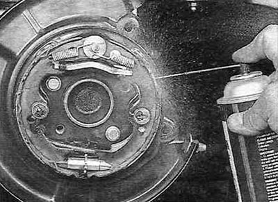
Figure 16.4. Before disassembling, wash the parking brake mechanism assembly with a special fluid for cleaning brake systems.
5. Follow the directions in the illustrations 16.5,a-x. Follow the order of actions in accordance with the numbering of the illustrations.
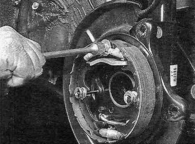
Figure 16.5,a. Remove the return spring of the rear parking brake shoe from the support pin...
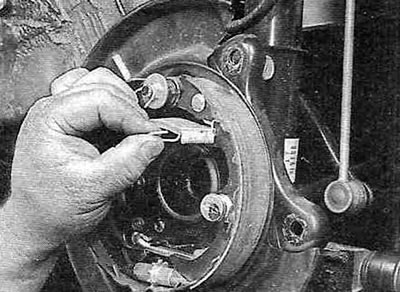
Figure 16.5, b....and unhook the return spring hook from the rear shoe.
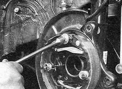
Figure 16.5, c. Remove the return spring of the front parking brake shoe from the support pin...
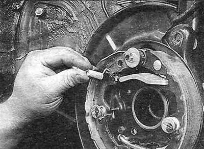
Figure 16.5, d....and unhook the return spring hook from the front shoe.
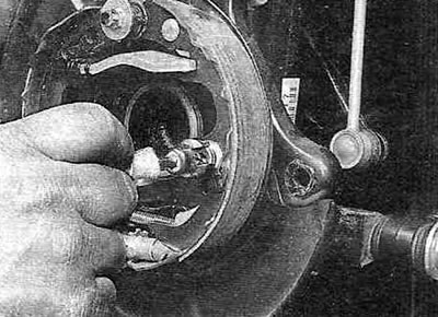
Figure 16.5,d. Remove the rear shoe pressure spring and take out the pin.
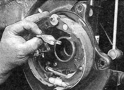
Figure 16.5,e. Remove the brake pad support plate.
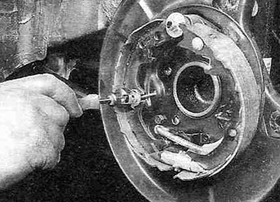
Figure 16.5, g. Remove the front shoe pressure spring and take out the pin.
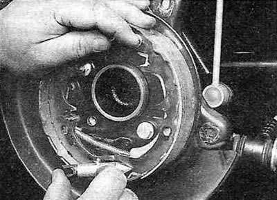
Figure 16.5, h. Remove the regulator and the tie spring (the tie spring is not visible in this illustration; it is located behind the regulator and is connected to both pads).
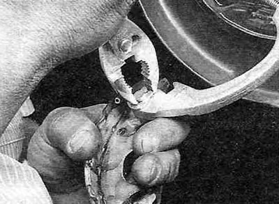
Figure 16.5, i. Remove the split washer-lock from the pivot pin on the edge of the rear shoe...
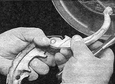
Figure 16.5,k....and remove the parking brake drive lever from the pivot pin.
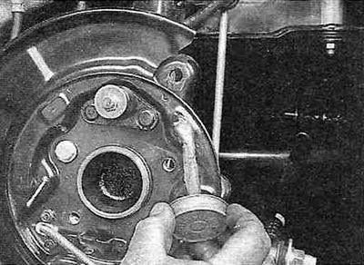
Figure 16.5,l. Apply a thin layer of high-temperature grease to the friction surfaces of the brake shield.
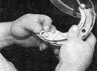
Figure 16.5, m. Place the parking brake drive lever onto the pivot pin and secure it with a new split locking washer.
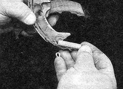
Figure 16.5,n. Attach the tension spring to the edge of the rear shoe...
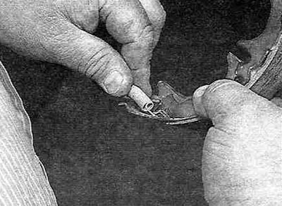
Figure 16.5, about... and the edge of the front shoe.
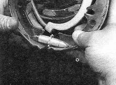
Figure 16.5, p. Move the pads apart and install the regulator. Make sure both ends of the adjuster are seated properly in the mating parts of the pads as shown.
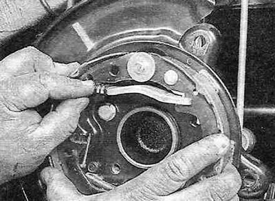
Figure 16.5, p. Set the pads to their working position, then install the support plate between them and hook the return spring to the front pad. Make sure both ends of the plate are seated properly in the pads as shown.
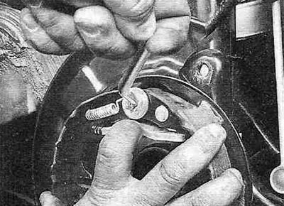
Figure 16.5,c. Hook the front shoe return spring to the support pin...
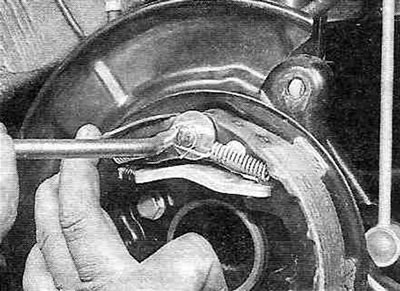
Figure 16.5, t....and hook the return spring of the rear shoe to the support pin.
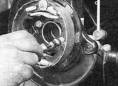
Figure 16.5, y. Install the rear shoe pressure spring...
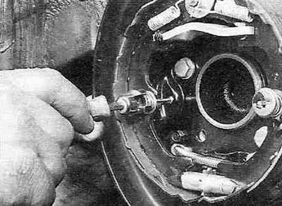
Figure 16.5, f....and the front brake shoe pressure spring.
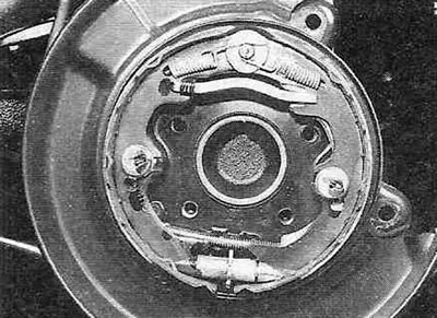
Figure 16.5,x. This is what the parking brake assembly should look like after assembly.
6. Install the brake disc. Temporarily tighten the three wheel nuts to tighten the wheel.
7. Remove the plug from the hole in the brake disc. Adjust the brake pad clearance by turning the ratchet wheel on the adjusting bolt using a special tool or screwdriver until the pads lock the disc (see figure 5.6,a,b). Rotate the ratchet wheel back eight notches and install the plug.
8. Install the caliper bracket and caliper (see paragraph 4). Tighten the mounting bolts to the torque specified in the Specifications in this chapter.
9. Install the wheel and tighten the mounting nuts to the torque specified in the Specifications chapter 1A or 1B.
10. Apply the parking brake, counting the number of clicks until it is fully engaged – there should be between five and seven. If this is not the case, adjust the parking brake as described in paragraph 12.