



Warning! Dust generated during normal operation of the brake system is harmful to health. Never blow it out with compressed air or inhale it. Always use a certified filter mask when working with the brakes. Never use petroleum-based solvents to clean the brake system. Use only brake system cleaner!
Caution! Parking brake pads must be replaced on both wheels at the same time; never replace the pads on just one wheel.
1. Remove the brake disc (see paragraph 5).
2. Assess the thickness of the friction material on the pads. If the thickness of the lining has reached 0.8 mm or become even smaller as a result of wear, the pads should be replaced.
3. Remove the hub assembly with the bearing (see chapter 10).
Note: It is possible to perform the pad replacement procedure without removing the hub assembly with bearings, although the space to work with is quite limited.
4. Wash the brake components using a brake system cleaner (Fig. 10.4).
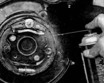
Fig. 10.4. After disassembling, clean the parking brake assembly using brake cleaning agents
5. Follow the accompanying photos when performing the brake pad replacement procedure (fig. 10.5, a-x). Do not break the prescribed sequence and read the captions under each figure.
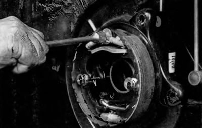
Fig. 10.5, a. Remove the return spring of the rear parking brake shoe from the support pin...
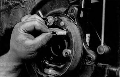
Fig. 10.5, b. and disconnect it from the rear shoe
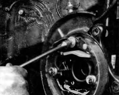
Fig. 10.5, c. Remove the return spring of the front parking brake adjustment from the support pin...
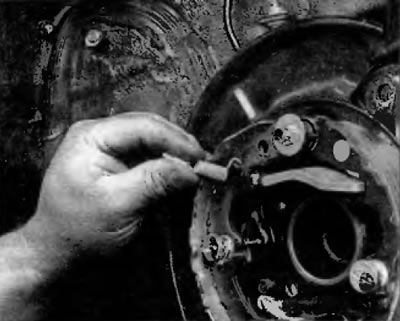
Fig. 10.5, g. and disconnect it from the front shoe
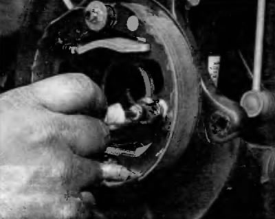
Fig. 10.5, d. Remove the rear shoe support post clamp and remove the post
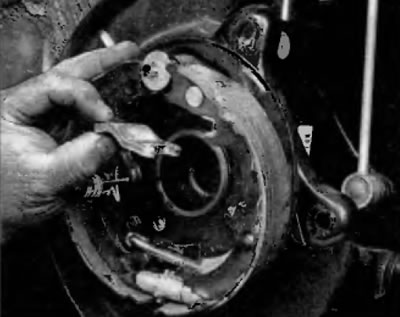
Fig. 10.5, e. Remove the spacer between the pads

Fig. 10.5, f. Remove the front shoe support strut clamp and remove the strut
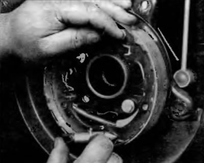
Fig. 10.5, 3. Remove the regulator and tension spring (the tension spring, which is not visible in this picture, is located behind the regulator and is connected to both pads)
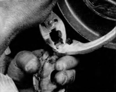
Fig. 10.5, i. Remove the C-clamp from the axle on the back of the rear shoe...
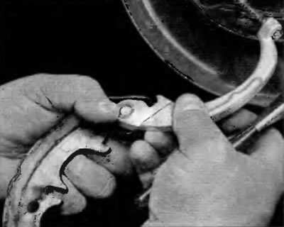
Fig. 10.5, k. and remove the parking brake drive lever from the axle
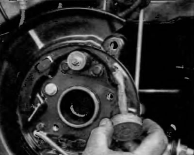
Fig. 10.5, l. Apply a thin layer of high-temperature grease to the contact surfaces of the brake shield
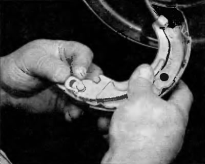
Fig. 10.5, m. Place the parking brake lever on the axle and install a new C-clamp
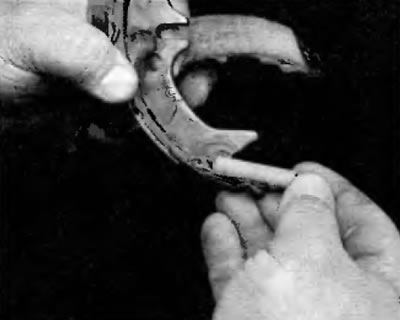
Fig. 10.5, n. Connect the tension spring to the back of the rear shoe...
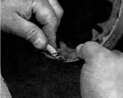
Fig. 10.5, about...to the back side of the front shoe
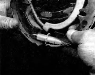
Fig. 10.5, item 1. Bring the pads to their normal position and install the adjuster. Make sure that both ends of the adjuster are properly engaged with the pads, as shown
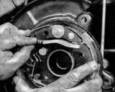
Fig.10.5, p. Install the pads in their original place and install the spacer and spring as shown. Make sure that the ends of the spacer are correctly engaged with the pads as shown
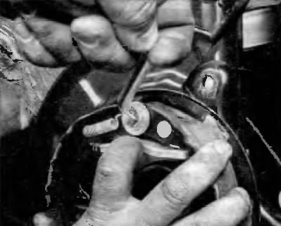
Fig. 10.5, p. Install the front shoe return spring...

Fig. 10.5, t....and the return spring of the rear shoe
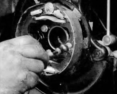
Fig. 10.5, y. Install the rear shoe support clamp...
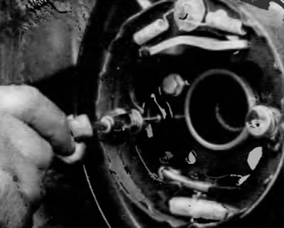
Fig. 10.5, f... and clamp of the front shoe support post
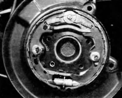
Fig. 10.5, x. This is what a properly assembled parking brake unit should look like
6. Install the brake disc. Temporarily tighten the three wheel nuts not the studs to hold the disc in place.
7. Remove the plug from the hole in the brake disc. Adjust the clearance between the shoes and the parking brake drum by turning the adjuster with a brake adjusting tool or screwdriver until the shoes come into contact with the drum built into the disc and the disc cannot be turned (fig. 5.6, a, b). Loosen the adjuster eight teeth and then install the plug into the hole.
8. Install the caliper bracket (fig. 5.2, b) and brake caliper (see paragraph 4). Tighten the bolts to the specified torque as shown in the Specifications at the beginning of this chapter.
9. Install the wheel and tighten the nuts to the specified torque specified in Specifications at the beginning of this chapter.
10. Apply the parking brake and count the number of clicks as it moves. There should be approximately 5-7 clicks. If this is not the case, adjust the parking brake as described in next paragraph.