



Vacuum brake booster
Operational check
1. Press the brake pedal several times (the engine is not working) and make sure that the pedal return stroke does not change.
2. Press the pedal and start the engine. If the pedal goes smoothly to the floor, the amplifier is working.
Leak test
3. Start the engine and turn it off after one or two minutes. Press the brake pedal smoothly several times. If the pedal stroke decreases with each press (the pedal becomes "higher"), the system is sealed.
4. Press the brake pedal with the engine running. While holding it down, turn off the engine. If after 30 seconds the pedal return stroke does not change, the booster is sealed.
(The original can be read on the website: www.TOYOTAMAN.ru)
Removal
5. The brake booster does not require any special attention during operation, except for monitoring the condition of the vacuum hoses. The amplifier is a non-separable unit. Considering its importance in the operation of the braking system, the faulty booster is replaced entirely with a new or refurbished unit.
6. Disconnect the hose going from the engine to the vacuum booster. Be careful not to damage the hose when disconnecting it from the vacuum booster fitting.
7. Remove the brake master cylinder (see paragraph 8). If you are working on a pre-2000 model, also remove the air intake duct and fuse/relay box.
8. Remove the left lower side trim panel from the instrument panel (see chapter 11).
9. Remove the brake pedal return spring.
10. Locate the fork rod connecting the brake pedal to the vacuum booster (see Figure 11.10).
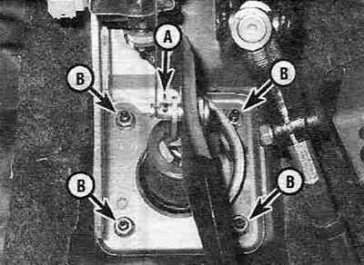
Figure 11.10. To disconnect the brake booster rod from the brake pedal, use pliers to remove the pin retainer (A) and pull the pin out of the fork. To disconnect the vacuum booster from the engine shield, unscrew the four mounting nuts (B).
Use pliers to remove the pin retainer and pull the pin out of the fork.
11. Unscrew the four nuts securing the booster to the brake shield (see Figure 11.10); you may need a flashlight for this (portable lamp).
12. Working under the hood, carefully remove the amplifier from the firewall studs and remove it from the engine compartment.
Installation
13. The procedure for installing the vacuum booster is generally performed in the reverse order of its removal. Tighten the brake pedal rod locknut securely. Tighten the vacuum booster mounting nuts to the specified torque Specifications.
14. If you are installing a new vacuum booster, check the clearance of its rod (see Figure 11.14,a) as follows:
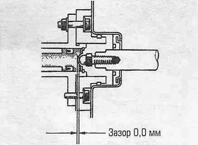
Figure 11.14,a. There should be no gap between the vacuum booster rod and the bottom of the socket in the master brake cylinder piston, but there should also be no tension. When tensioned, the brake pedal will be excessively tight; with a gap, the pedal stroke will be increased.
- Measure the distance the vacuum booster rod protrudes beyond the mating surface of the master cylinder, including the gasket (see Figure 11.4,b). Record the measurement result. Let's denote it by the letter A.
- Measure the distance between the master cylinder mounting flange and its outer plane (see Figure 11.14,b). Record the measurement result. Let's denote it by the letter B.
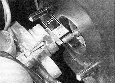
Figure 11.14, b. Measure the distance by which the vacuum booster rod protrudes beyond the mating surface of the master cylinder, including the gasket.
- Measure the distance between the outer surface of the master cylinder and the bottom of the socket in its piston (see Figure 11.14,c). Record the measurement result. Let's denote it by the letter C.
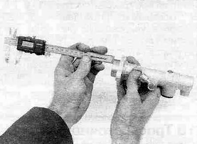
Figure 11.14, c. Measure the distance between the master cylinder mounting flange and its outer plane.
- Subtract the value of B from the value of C, then subtract the value of A from the result obtained. This value will be the vacuum booster rod clearance.
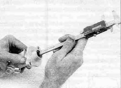
Figure 11.14, d. Measure the distance between the outer plane of the master cylinder and the bottom of the seat in its piston.
- Compare the value you calculated with the value prescribed Specifications. If necessary, adjust the protruding length of the vacuum booster rod to achieve the required clearance, as shown in the figure 11.4, d.
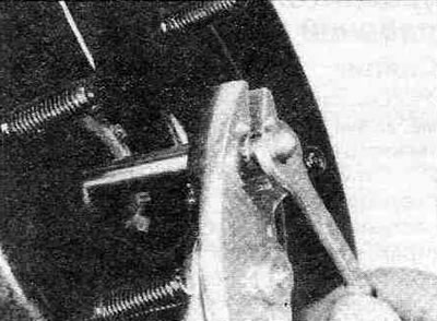
Figure 11.14, d. To adjust the protrusion length of the vacuum booster rod to set zero clearance, turn the rod in one direction or another, holding the knurled section of the latter with pliers.
15. After the final installation of the master brake cylinder, all hoses and pipes, it is necessary to adjust the height of the brake pedal and its free travel. Bleed the brake system. See the relevant paragraphs of this chapter.