
Clutch interlock switch
The switch is designed to block the start of the engine if the clutch pedal is not depressed.
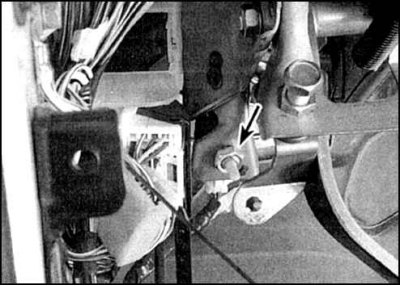
Clutch interlock switch (indicated by an arrow) mounted on a bracket at the top of the pedal, fastened with 2 nuts that adjust its position relative to the pedal.
Check, adjustment and replacement
1. Make sure the engine only starts when the pedal is depressed.
2. Otherwise, the switch is defective. Check for the presence of voltage at the switch.
3. If there is voltage, then check the ground connection of the second output of the switch with the pedal released.
4. If the switch circuit is faulty, repair the problem and recheck the switch.
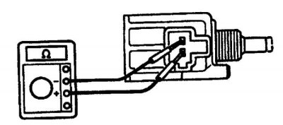
5. If the circuit is OK, then check the closure of the switch contacts. When the pusher is pressed, the contacts should close, when the pusher is released, the contacts open. Otherwise, replace the switch.
Start release switch
This switch allows the engine to be started without depressing the clutch pedal, which may be necessary in difficult driving conditions (e.g. uphill). The switch button is located on the left side of the front panel, the override switch itself is part of the clutch lockout switch.
Check, adjustment and replacement
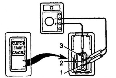
1. Move the button to the Off position and connect (+) - the output of the ohmmeter to the output 2 of the switch, and (-) - ohmmeter output - to output 1. Between these outputs, the ohmmeter should show a gap.
2. In the same position of the button, attach (+) - the output of the ohmmeter to the output 3 of the switch, and (-) - ohmmeter output - to output 1. Between these outputs, the ohmmeter should show a gap. There should also be no circuit between pins 2 and 3.
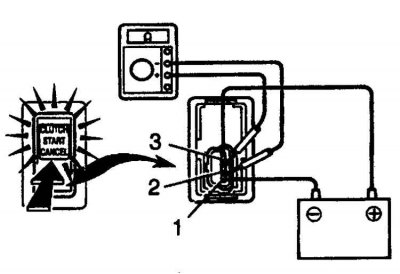
3. Apply 12V power to pin 3, and (-) connect batteries to terminal 1 (+) - connect the output of the ohmmeter to the output of 2 switches, and (-) - ohmmeter output - to output 1. When the button is pressed (in the On position) between these leads, the ohmmeter should show a circuit.
4. When the switch is in the Off position, there should be an open between these pins.
5. Disconnect the battery and turn the switch to the On position. Between pins 1 and 2, the ohmmeter should show a gap.
6. If results of checks differ from described above replace the switch.
7. To adjust, loosen the lock nut and rotate the switch until the pusher protrudes 7.5–8.3 mm relative to the lock nut.
8. To replace, remove the lower trim, disconnect the connector, unscrew the locknut and remove the switch. Installation is carried out in the reverse order.