



Contents: Removal ↓ Installation ↓
Warning! Dust generated during normal operation of the brake system is harmful to health. Never blow it out with compressed air or inhale it. Always use a certified filter mask when working on the brakes. Under no circumstances use petroleum-based solvents to clean the brake system. Use only brake system cleaner!
Caution: If the vehicle is equipped with electronically controlled air suspension, turn off the height control switch before raising the vehicle.
Note: The following procedure applies to 2WD models only. On 4WD models, pressing the hub and bearing out of the rear hub carrier requires special tools and experience, so this job should be left to a professional. However, the hub carrier and hub can be removed as a single unit and then taken to your dealer's service department or other qualified service station. For the hub carrier and rear hub removal procedure, refer to paragraph 14.
Note: The rear hub assembly with bearing is not serviceable. If any component is found to be faulty, the entire unit must be replaced.
Removal
1. Loosen the wheel nuts, lift the car and place reliable supports under it. Remove the wheel.
2. Remove the disc from the hub and disconnect the wheel speed sensor electrical connector (see chapter 9).
3. Remove the four bolts securing the hub to the hub support, gaining access by rotating the hub so that the large round cutout exposes each bolt in turn (Fig. 13.3).
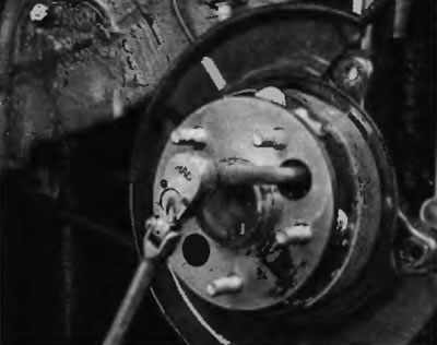
Fig. 13.3. To remove the four bolts that secure the hub assembly with the bearing to the rear hub support, rotate the hub flange and align one of the holes in the flange with each of the bolts
4. Remove the hub assembly with the bearing from its standard location, removing it through the parking brake assembly.
Installation
5. Install the hub and bearing assembly onto the hub carrier and align the holes in the brake shield. Install the bolts. A magnet will be helpful when guiding the bolts into place through the hub flange. Once all four bolts are installed, tighten them to the specified torque as shown in Specifications at the beginning of this chapter.
6. Install the disc and caliper. Install the wheel. Lower the vehicle and tighten the wheel nuts to the specified torque as shown in Specifications at the beginning of this chapter.