
Attention! If the vehicle is equipped with electronically controlled air suspension, turn off the suspension height control switch before raising the vehicle.
1. Loosen the wheel nuts, raise the vehicle and securely support it under it. Remove the wheel.
Note. If you are going to remove the ball joint with a puller (as described in p.p. 9-13), before lifting the vehicle, loosen the axle shaft/hub nut (see chapter 8).
Replacement with fork puller
Warning. The following procedure is the fastest way to disconnect the ball joint from the steering knuckle, but it is more likely to damage the ball joint boot. If you want to keep the case, go to step 9.
2. Remove the cotter pin from the ball joint pin and loosen the nut a few turns (but don't unscrew it completely yet).
3. Separate the ball joint from the steering knuckle using a ball joint fork puller. Loosen the nut on the ball joint pin.
4. Turn out a bolt and turn away nuts of fastening of the spherical hinge to the cross-section lever (pic. 5.3, a). Separate the ball joint from the control arm with a pry bar (pic. 5.3, b).
5. To install the ball joint, place it in the steering knuckle and screw on the nut, but do not tighten it yet.
6. Connect the ball joint to the transverse arm, screw in the bolt and screw the nuts. Tighten them to the prescribed torque specified in Specifications at the beginning of this chapter.
7. Tighten the nut on the ball joint pin to the specified torque as specified in Specifications at the beginning of this chapter, and insert a new cotter pin. If the hole for the cotter pin does not line up with the slots on the nut, tighten the nut further until it reaches the required position - do not loosen the nut to install the cotter pin.
8. Install the wheel and tighten the wheel nuts. Lower the vehicle and tighten the wheel nuts to the specified torque specified in Specifications at the beginning of this chapter.
Replacement with 2-jaw puller
9. Remove the wheel speed sensor (see chapter 9).
10. Separate the transverse arm from the ball joint (see paragraph 5).
11. Pull the outer end of the axle shaft out of the steering knuckle (see chapter 8) and hang the axle shaft with a piece of wire.
12. Remove the cotter pin on the ball joint pin and loosen the nut a few turns (but don't unscrew it completely yet).
13. Install the small puller (pic. 6.13) and pull the ball joint pin out of the steering knuckle.
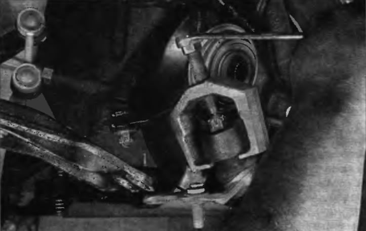
Pic. 6.13. To disconnect the ball joint from the steering knuckle, install a small puller and release the ball joint pin
14. Turn away a nut and remove the spherical hinge.
15. Install a new ball joint in the swivel bag and tighten the nuts to the specified torque listed in the Specifications at the beginning of this chapter. Install a new pin. If the hole for the cotter pin does not line up with the slots on the nut, tighten the nut further until it reaches the required position - do not loosen the nut to install the cotter pin.
16. Insert the outer end of the axle shaft into the steering knuckle and tighten the nut. Tighten it securely, but don't try to tighten it all the way yet.
17. Connect the ball joint to the lower arm and tighten the fasteners to the prescribed torque specified in Specifications at the beginning of this chapter.
18. Install the wheel speed sensor.
19. Establish a wheel and screw nuts of its fastening. Lower the vehicle and tighten the wheel nuts to the specified torque specified in Specifications at the beginning of this chapter.
20. Tighten the axle shaft/hub nut to the specified torque as specified in Specifications at the beginning of this chapter, and then stop it with a punch (see chapter 8).