
Attention! If the vehicle is equipped with electronically controlled air suspension, turn off the suspension height control switch before raising the vehicle.
Application. Note that the painted markings on all rear suspension arms face the rear of the vehicle. If the markings are missing or not visible, mark the levers to allow the levers to be repositioned in their original position.
Removing
1. Loosen the rear wheel nuts, raise the rear of the vehicle and place secure supports under it. Remove the rear wheel.
Front wishbone (№1) (two wheel drive)
2. Remove the rear stabilizer (see paragraph 9).
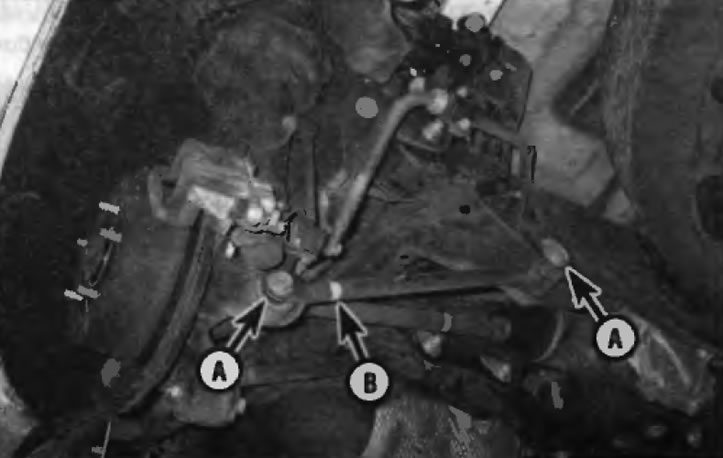
3. Remove the fastening elements of the lever to the hub support and the rear cross member, and then remove the lever (pic. 12.3).
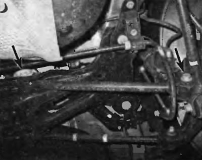
Pic. 12.3. Fastening elements of the front transverse arm on models with a drive and two wheels
Front wishbone (N°1) (four-wheel drive)
4. On 4WD models, the rear cross member must be lowered to access the bolt on the inner end of the front transverse arm.
5. Disconnect the trailing arms from the hub support on both sides of the vehicle (see paragraph 11).
6. Remove the center section of the exhaust system and the rear exhaust pipe (see chapter 4).
7. Remove cardan shaft assembly with intermediate support (see chapter 8).
8. Remove both rear axle shafts (see chapter 8).
9. Disconnect the transverse levers from the supports of both hubs.
10. Place a floor jack under the center of the cross member (under the differential), then release and remove the crossmember-to-body fasteners (pic. 12.10, a, b). Gently lower the rear cross member with the jack (do not get under the car if it is only supported by a jack) before gaining access to the transverse arm bolts. Remove the bolts (pic. 12.10, a, b).
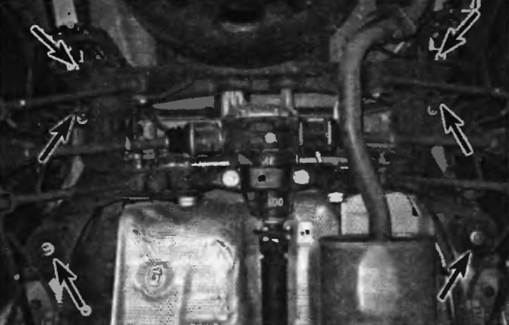
Pic. 12.10, a. Elements of fastening of a back crosspiece on all-wheel drive models
Pic. 12.10, b. Fastening elements of the front transverse arm on all-wheel drive models
Warning. For this procedure, it is recommended to use a floor jack with a gearbox adapter head to securely support the cross member.
Rear wishbone (№ 2) (four-wheel drive)
11. Remove the rear stabilizer (see paragraph 9).
12. Not 2003 and earlier models, mark the position of the eccentric bolts (at both sides), to keep the toe adjustment (pic. 12.12).
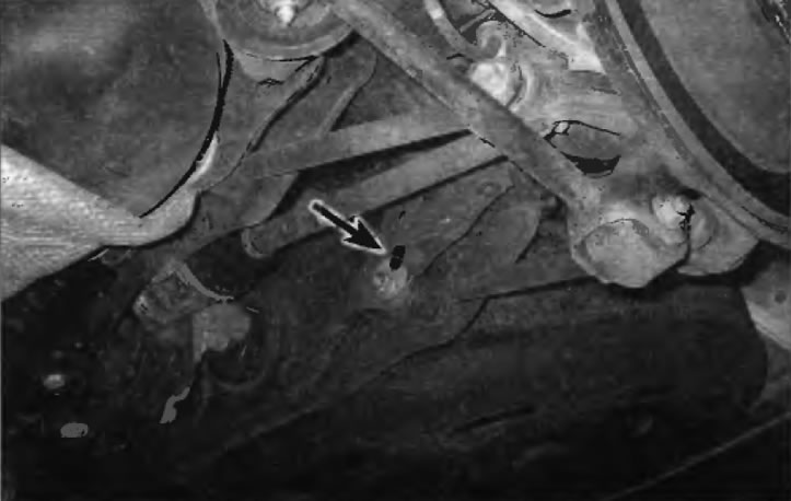
Pic. 12.12. Eccentric bolt with a mark of its position relative to the rear cross member
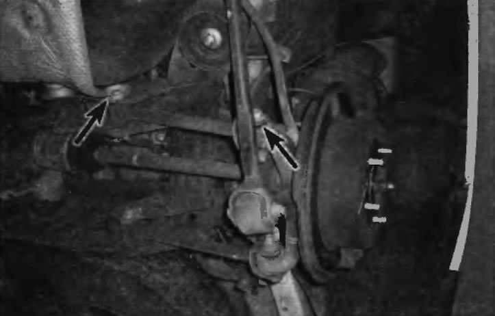
13. Remove the lever mounting elements from the hub support and cross member, then remove the lever (pic. 12.13).
Pic. 12.13. Elements of fastening of the rear transverse arm (A) on all wheel drive models. Pay attention to the mark made by the paint (IN), facing towards the back of the car
Note. On Lexus vehicles with electronically controlled air suspension, before removing the fasteners, disconnect the linkage of the ride height sensor from the lever.
Installation
Application. When installing any rear suspension arms, loosely tighten all bolts, adjust to normal ground clearance, and only then fully tighten the bolts.
14. Installation is performed in the reverse order of removal. Tighten all bolts/nuts to the specified torque specified in Specifications at the beginning of this chapter.
Note. When reinstalling the suspension arms, the painted factory markings on the arms must face the rear of the vehicle.
15. Establish a wheel and screw nuts of its fastening. Lower the car. Tighten the wheel nuts to the specified torque as specified in Specifications at the beginning of this chapter. If you are working with an all-wheel drive model, tighten the axle shaft/hub nut to the specified torque specified in Specifications at the beginning of this chapter.
16. Check the rear wheel alignment by contacting the dealer's technical service department or a specialized service station.