
Attention! Cars are equipped with security systems (SRS), including airbags and seat belt tensioners. Before carrying out work near the shock sensors, the instrument panel and the steering column, first disconnect the negative and then the positive terminals from the battery and wait 2 minutes. This will prevent unauthorized deployment of the airbags and deployment of the seat belt pretensioners, which could cause injury.
Relays for direction indicators and emergency light signaling are made as one combined unit.
When the relay is operating in the car, clicks should be heard. If, when the direction indicators are turned on on one or the other side of the car, the relay operates at an increased frequency, then one of the direction indicator lamps has burned out, and the serviceable lamp flashes at double the frequency.
If the turn signal lights on both sides of the vehicle do not flash, the fuse may have blown, the turn signal switch or relay may have failed, or there may be an electrical circuit problem. If a fuse is blown, check the condition of the electrical circuit before installing a new fuse.
Replace the turn signal and hazard warning relay as follows:
Disconnect the relay electrical connector.
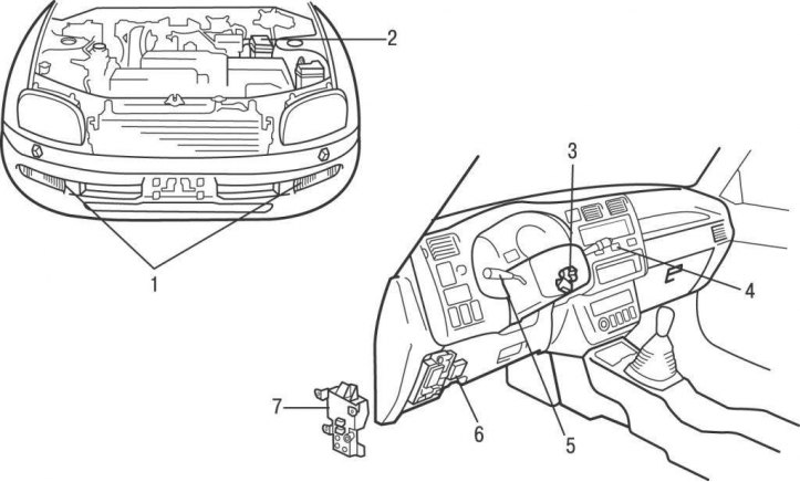
Pic. 15.14. The location of the turn signal and hazard warning light relay on models up to 2001: 1 - fuse in the relay and fuse box No. 2; 2 - front direction indicators and emergency light signaling; 3 - relay of direction indicators and emergency light signaling in block No. 5; 4 - ignition lock; 5 - emergency light switch; 6 - switch of direction indicators; 7 - fuse in the fuse box
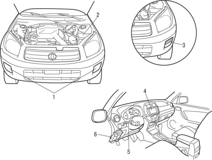
Pic. 15.15. Location of turn signal and hazard warning light relay on models from 2001: 1 - front direction indicators and emergency light signaling; 2 - fuse in the engine compartment fuse box; 3 - front fog lamp with direction indicator; 4 - emergency light switch; 5 - switch of direction indicators; 6 - relay of direction indicators and emergency light signaling
Remove the relay from the bracket located under the instrument panel, to the right of the steering column (pic. 15.14, 15.15).
Install the relay in the reverse order of removal.