
- switches large currents remotely from the circuit in which that current flows, allowing the use of thinner wires and switch contacts in the main circuit;
- unlike a mechanical switch, which has one control input, it can switch over several control inputs;
- timer and thus sets the wiper interval.
If the electrical circuit controlled by the relay fails, and the cause of the problem is probably the relay, listen for the operation of the relay while the system is on. If the relay is working properly, you should hear a click when it turns on. If the relay is OK, then the cause of the malfunction lies in the elements or connecting wires. If the relay does not work, it means that it does not receive the main power supply or control pulse, or the relay itself is faulty.
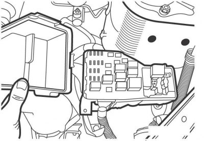
Pic. 15.8. Location of the fuse and relay box in the engine compartment on models from 2001
Most of the relays are located in the fuse and relay box in the engine compartment (see fig. 5.8).
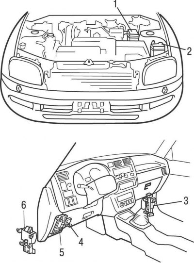
Pic. 15.10. Location of specialized relays in models up to 2001: 1 - relay block No. 2; 2 - relay block No. 6; 3 - connecting block No. 4; 4 - fuse block; 5 - connecting block No. 1; 6 - relay block No. 6
Some specialized relays are located separately or in separate blocks under the instrument panel and in the engine compartment (pic. 15.10).
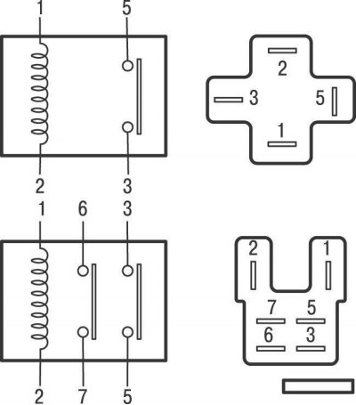
Pic. 15.11. Relay with permanently open contacts: A - when voltage is applied to the relay winding (1 and 2), relay contacts 3 and 5 close; B - when voltage is applied to the relay winding (1 and 2), executive contacts 3 and 5, and 6 and 7 are closed in pairs
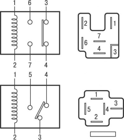
Pic. 15.12. Relay with changeover contacts: A - when voltage is applied to the relay winding (1 and 2), relay contacts 3 and 4 open and contacts 6 and 7 close
Four types of relays are used on cars: permanently closed or open contacts and changeover contacts (pic. 15.11, 15.12). On the cases of some relays, an electrical diagram of the relay with contact numbers is shown.
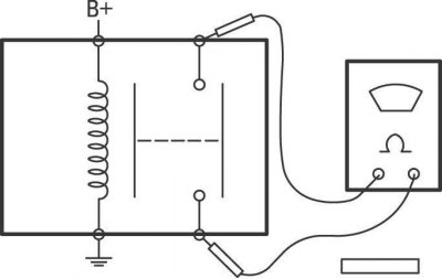
Pic. 15.13. Scheme for testing relays with permanently open contacts
To test the relay, connect an ohmmeter to its contacts, while the ohmmeter should show an open circuit (pic. 15.13). Then, with one additional wire, connect the contact of the relay winding with «weight», and with the second additional wire, connect the second contact of the relay winding to the positive terminal of the battery, while the relay should turn on (click) and the ohmmeter should show a short circuit (resistance 0 ohm). Otherwise, the relay is defective and must be replaced.