



Contents: Removal ↓ Installation ↓
Removal
Proceed with removal in the following order:
- remove the timing chain and sprocket from the crankshaft;
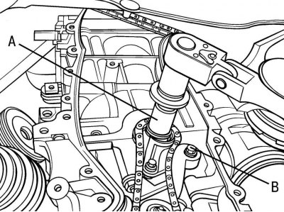
Figure 3.90. Setting the crankshaft key to the left horizontal position (A) after turning the engine crankshaft 90° counterclockwise and positioning the bolt (B) for securing the oil pump drive chain tensioner
- turn the engine crankshaft 90° counterclockwise (from TDC) and install key A (figure 3.90) crankshaft to the left horizontal position, then unscrew bolt B and remove the oil pump drive chain tensioner;
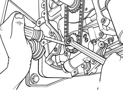
Figure 3.91. Removing the sprocket with the oil pump drive chain from the crankshaft
- remove the sprocket with the oil pump drive chain from the crankshaft (figure 3.91);
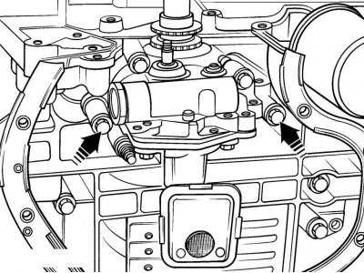
Figure 3.92. Location of oil pump mounting bolts
- unscrew the 3 bolts securing the oil pump to the cylinder block (figure 3.92). Use a screwdriver to separate the oil pump from the cylinder block.
Installation
Using a hard plastic or wooden scraper, remove any remaining old sealant from the mating surfaces of the oil pump and cylinder block and clean them with solvent.
Check the oil pump for damage.
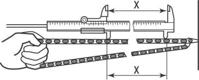
Figure 3.62. Measuring the distance between chain links: X = 122.6 mm for timing chain between 16 rollers or 8 chain links; X = 52.4 mm for oil pump drive chain between 8 rollers or 4 chain links
Check the chain links for cracks, wear on the rollers and side plates. Check the condition of the sprocket teeth, which should be symmetrical. Tighten the chain and measure the distance between 8 rollers or 4 links of the chain, which should be 52.4 mm (see Figure 3.62). Perform this test on several sections of the circuit. If the chain has lengthened, replace the chain and sprockets as a set.
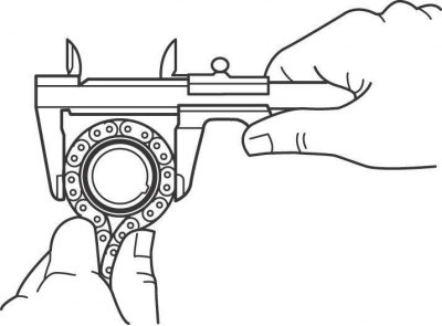
Figure 3.63. Measuring the sprocket diameter by the chain rollers
Wrap each sprocket with chain and measure the sprocket diameter against the chain rollers (see figure 3.63). If the resulting dimension exceeds the minimum chain diameter, replace the chain and sprockets as a set.
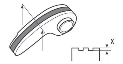
Figure 3.93. Locations for measuring the depth of the notches on the oil pump drive chain guide: X = no more than 0.5 mm
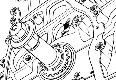
Figure 3.94. Location of the chain guide lubrication hole
Publication Reprinted from a web portal toyotaman.ru
Check the chain guide for excessive wear. Please note that minor wear on the guide is normal. The depth of the grooves on the chain guide should be no more than 0.5 mm (figure 3.93). If excessive wear is present, check the chain guide oil hole on the front of the cylinder block for dirt or clogging (figure 3.94). If the hole is blocked, the wear on the timing chains and oil pump will increase dramatically.
Perform installation in the following order:
- fill the oil pump with oil by pouring a small amount of clean engine oil into the pump inlet and turning the pump drive shaft;
- install the oil pump with a new gasket on the cylinder block and secure it with bolts, tightening them crosswise to a torque of 19 N·m;
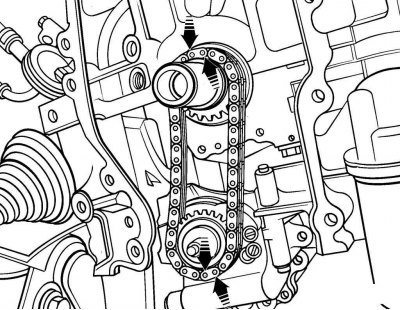
Figure 3.95. Alignment of color marks on the chain with marks on the sprockets
- make sure the crankshaft is turned 90° counterclockwise, the crankshaft key is set to the left horizontal position and the oil pump drive sprocket is turned with the mark facing up. Install the oil pump drive chain onto the sprockets so that the color marks on the chain align with the marks on the sprockets (figure 3.95);
- screw in and tighten the oil pump sprocket mounting bolt to a torque of 30 N·m;
- install the chain tensioner and secure it with the bolt, tightening the bolt to a torque of 12 Nm.
Further installation is carried out in the reverse order of removal, taking into account the following.
Check and, if necessary, top up the oil level to the correct level.
Start the engine and check for oil pressure and leaks.