
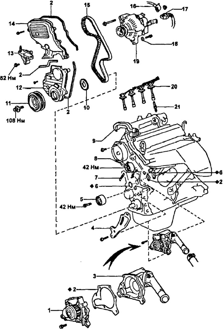
Parts for removing and installing the coolant pump (3S-FE; 4S-FE; 3S-GE). 1 - coolant pump; 2 - gasket; 3 - coolant pump cover; 4 - generator adjusting bracket; 5 - intermediate pulley; 6 - ring seal; 7 - roller spring - tensioner; 8 - tension roller; 9 - wire harness protection; 10 - timing belt guide; 11 - crankshaft pulley; 12 - cover No. 1 of the timing belt; 13 - right engine mount; 14 - cover No. 2 of the timing belt; 15 - timing belt; 16 - generator wire; 17 - generator connector; 18 - plate washer (models with air conditioning); 19 - generator; 20 - high-voltage wires; 21 - spark plug.
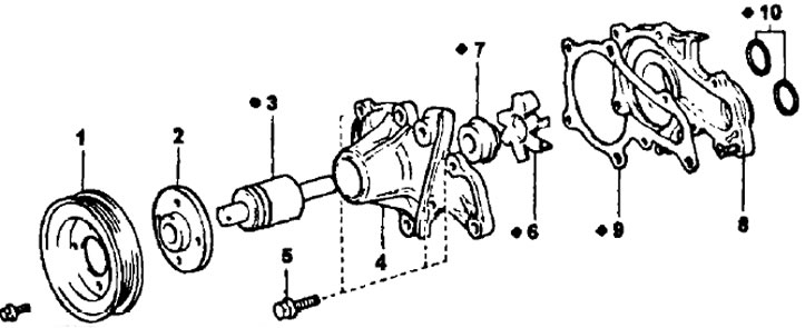
coolant pump (4A-FE; 5E-FE; 7A-FE). 1 - coolant pump drive pulley; 2 - pump drive pulley hub; 3 - bearing; 4 - pump housing; 5 - a bolt of fastening of the case of the pump (M3=9.1 Nm); 6 - pump rotor (impeller); 7 - stuffing box; 8 - pump cover; 9 - pump cover gasket; 10 - sealing rings of the pump cover.
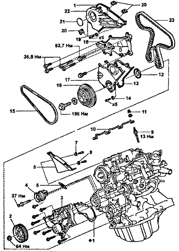
Parts for removing and installing the coolant pump (2C; 2S-T). 1 - gasket; 2 - toothed pulley of the injection pump drive; 3 - coolant pump; 4 - tension roller; 5 - tension spring; 6 - cover No. 3 of the timing belt; 7 and 8 - washers; 9 - glow plug; 10 - tire of glow plugs; 11 - insulator washer; 12 - timing belt guide; 13 - gasket; 14 - washer; 15 - generator drive belt; 16 - crankshaft pulley; 17 - timing belt cover No. 2; 18 - engine support bracket; 19 - washer; 20 - clamp; 21 - technological cover; 22 - timing belt cover; 23 - timing belt.
Removing the coolant pump
1. Drain the coolant.
(4A-FE, 7A-FE)
2. Remove the following parts (see paragraphs 1,2, 3, 5 and 6 of the subsection "Removing the timing belt").
- A) Alternator drive belt and coolant pump pulley.
- b) Cylinder head cover.
- V) Protective covers No. 2 and No. 3 of the timing belt.
- G) Electrical protective cover.
3. Remove the oil dipstick assembly.
4. Remove the coolant pump and coolant inlet No. 2 following the sequence:
- A) Disconnect the coolant temperature sensor connector.
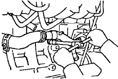
- b) Unscrew the two nuts securing the inlet pipe No. 2 to the cylinder head.
- V) Unscrew the three pump mounting bolts and remove the coolant pump together with the inlet pipe No. 2.
- G) Remove the O-ring gasket.
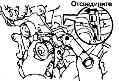
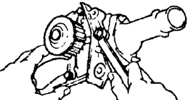
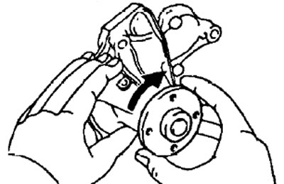
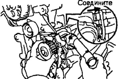
- d) Separate the pump from the #2 inlet as shown in the figure.

(3S-FE, 3S-GE, 4S-FE)
2. Remove the timing belt (Chapter "timing belt" subsection "Removing the timing belt").
Note: Do not remove the camshaft, oil pump and crankshaft sprocket.
3. Turn away a bolt and remove an adjusting arm of the generator.
3S-FE, 4S-FE

3S-GE
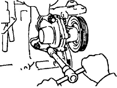
4. Remove the water pump and cover assembly.
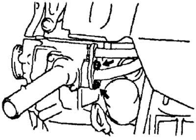
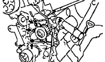
- A) Loosen the two nuts on the coolant bypass pipe.
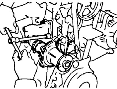
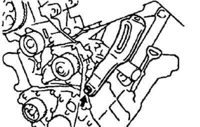
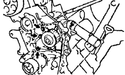
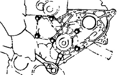
- b) Remove the three bolts in the sequence shown in the figure.
- V) Disconnect the water pump cover from the bypass tube and remove the water pump and cover assembly.
- G) Remove the gasket and two O-rings from the water pump and bypass tube.
5. Turn away three bolts, remove the pump of a cooling liquid and a lining.
(2S, 2S-T)
1. Drain the coolant.
2 Remove the timing belt.
3. Remove the toothed pulley of the injection pump drive and unscrew the nuts of the injection pump.
4. Turn out bolts and remove the pump of a cooling liquid.
(5E-FE)
2. Remove the generator.
3. Remove the intake manifold bracket by removing the two bolts and nut.
4. Remove the inlet pipeline of the cooling system.
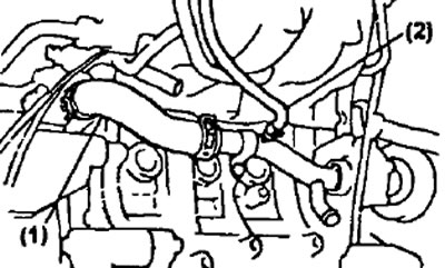
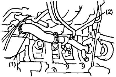
- A) Disconnect the following hoses:
- (1) Liquid pump inlet hose on thermostat side;
- (2) Coolant bypass hose.
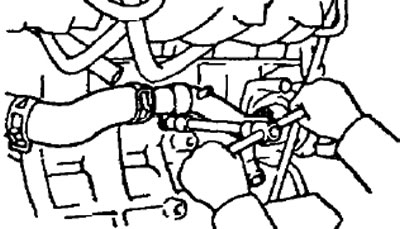
- 6) Loosen the bolt, remove the fluid pump inlet hose and O-ring.
5. Remove the dipstick guide and alternator adjusting bracket.
6. Remove the coolant pump by removing the bolt and two nuts.
Checking the coolant pump
1. Visually check that there are no coolant leaks from the connections and air hole.
2. Rotate the pulley and check that the pump shaft rotates easily and silently. If there is a problem, replace the pump assembly.
Installing the coolant pump
(4A-FE, 7A-FE)
1. Connect the pump to inlet #2.
2. Install the pump assembly with inlet #2 on the engine, installing a new o-ring on the cylinder block and a new gasket on the cylinder head, with the marking protrusion of this gasket facing up, as shown in the figure.
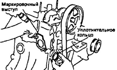
Install and tighten the bolts and nuts of the pump assembly (together with the inlet pipe No. 2).
- Torque:
- bolts - 14 Nm
- nuts - 15 Nm
3. Install the oil dipstick assembly with a new O-ring in place on the guide.
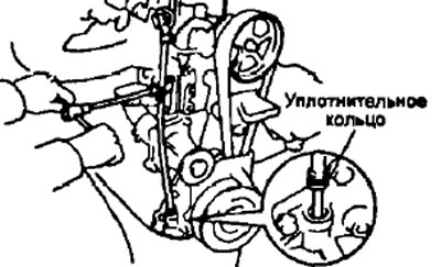
Tighten the mounting bolt (9.3 Nm)
4. Install the following parts (see paragraphs 9, 11, 12, 13 and 14 of the subsection "Timing belt installation"):
- A) Electrical protective cover.
- b) Protective covers No. 2 and Ne3 of the timing belt.
- V) Cylinder head cover.
- G) Alternator drive belt and coolant pump pulley.
(3S-FE, 3S-GE, 4S-FE)
5. Install the water pump to the cover by installing a new gasket and tightening the three bolts.
- Tightening torque - 9 Nm
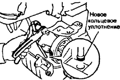
6. Install the water pump and cover assembly.
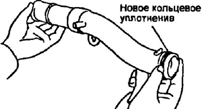
- A) Install a new O-ring and gasket to the water pump.
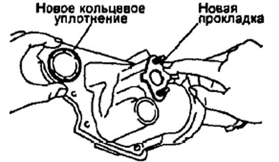
- b) Install a new O-ring on the coolant overflow pipe.
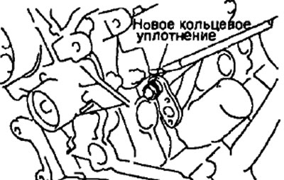
- V) Apply soapy water to the O-ring of the coolant bypass pipe.
- G) Connect the bypass tube to the coolant pump.
- d) Install the water pump and tighten the three bolts in the sequence shown in the illustration.
- Tightening torque - 9 Nm
- e) Tighten the two nuts of the coolant bypass pipe.
- Tightening torque - 9 Nm
7. Install the alternator adjustment bracket by tightening the bolt.
- Tightening torque - 27 Nm
8. Install the timing belt (see subsection "Timing belt installation").
(2S, 2S-T)
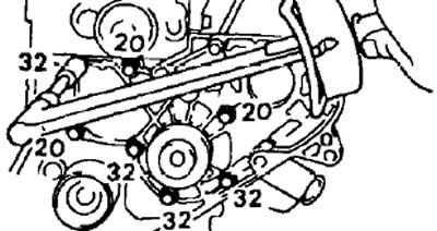
9. Install a new gasket and coolant pump. Tighten the mounting bolts.
- Tightening torque - 18 Nm
Note: bolt lengths (in mm) shown in the figure.
10. Establish a gear pulley of a drive of TNVD and TNVD.
11. Install the timing belt.
(5E-FE)
12. Install the coolant pump.
- A) Remove the old gasket material and be careful not to drip oil onto the surface. Clean both seal faces with a non-residue solvent.
- b) Apply sealant to the water pump recess.
Note:
- Do not apply too much sealant.
- The mating parts must be assembled within 5 minutes after applying the sealant. Otherwise the material must be removed and reapplied
- Do not add coolant within 2 hours after installation is completed.
- V) Install the water pump by tightening the bolt and two nuts.
- Tightening torque - 19 Nm
13. Install the dipstick guide and alternator adjustment bracket.
- A) Install a new O-ring on the dipstick guide.
- b) Apply a solution of soapy water to the O-ring
- V) Insert the dipstick guide and tighten it with the alternator adjusting bracket bolt and install the dipstick guide clip.
- Tightening torque - 19 Nm
- G) Install the oil dipstick.
14. Install the coolant pump inlet hose.
- A) Install a new O-ring on the inlet hose on the thermostat side.
- b) Apply a small amount of soapy water to the O-ring.
- V) Install the inlet hose and tighten the bolts.
Note: Improper installation of the inlet hose at an angle or twist can damage the O-ring.
- Tightening torque - 8 Nm
- G) Connect the following hoses:
- (1) Liquid pump inlet hose on thermostat side;
- (2) Coolant bypass hose.
15. Install the intake manifold bracket by tightening the bolt and nut.
- Tightening torque - 19 Nm
16. Install the generator.
(All engines)
17. Fill the system with coolant (see section "Maintenance and general inspection and adjustment procedures").
18. Start the engine and check for coolant leaks.