
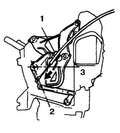
Typical location of cables for controlling the air conditioning unit
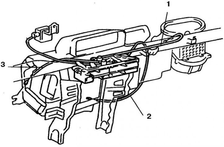
1. Air damper cable
2. Mixing flap cable
3. Ventilation flow control cable
Removing
1. Disconnect the battery from the ground.
2. Remove the center console trim (see subsection 10.23).
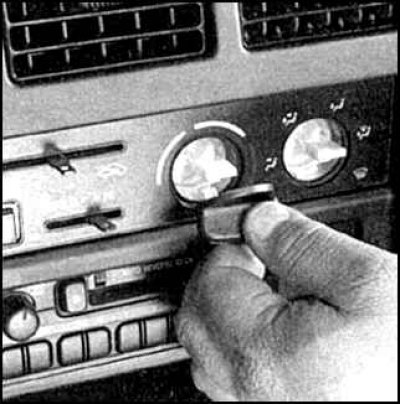
3. Remove the handles.
4. Loosen the control panel screws.
5. Pull the panel towards you, turn the flags and disconnect the cables, disconnect the connectors.
Installation
1. Assembly is carried out in the reverse order.
2. Adjust cables.
3. Check heater operation.
Adjustment
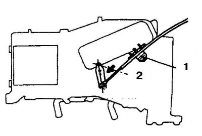
Air damper adjustment
1. Clamp
2. FRESH position (fully open)
3. RECIRC Statement (completely closed)
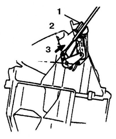
Mixing flap cable adjustment
1. Clamp
2. COOL position / WARM position
Heating Cable Adjustment
1. Clamp
2. FACE position (on the face)
3. DEF position
1. Move the control handles to the RECIRC, COOL, DEF positions.
2. To adjust the air damper cable, move the lever to the FRESH position, attach the cable and tighten the clamp (see fig. Air damper adjustment).
3. To adjust the mixing flap control cable, move the lever to the COOL position, attach the cable and tighten the clamp while pressing the cable sheath (see fig. Mixing flap cable adjustment).
4. To adjust the heating cable, move the lever to the DEF position (defrosting), attach the cable and tighten the clamp (see fig. Heating Cable Adjustment).
Circuit Check
Cabin air conditioning wiring diagram
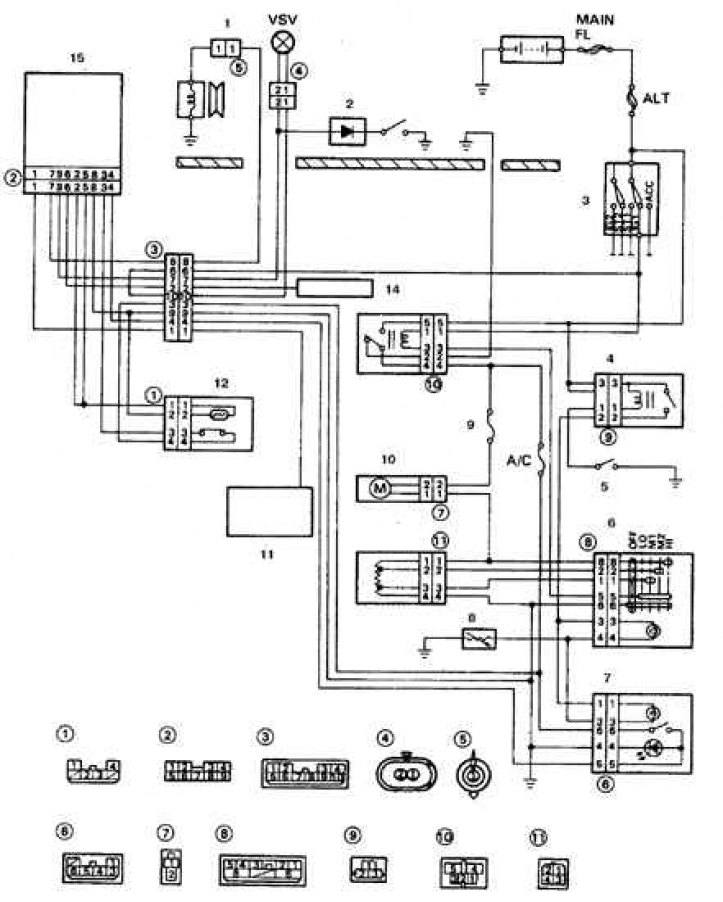
1. Electromagnetic clutch; 2. Processor control unit; 3. Ignition switch; 4. Tail light relay; 5. Rear light switch; 6. Fan switch; 7. Air conditioner switch; 8. Rheostat; 9. Heater fuse; 10. Electric motor; 11. Electronic module (on cars with a / t); 12. Pressure switch and thermal switch; 13. Main heater relay; 14. Impulse ignition unit; 15. Amplifier
Rear heater switch test table
| Switch position | Verifiable Conclusions | Tester reading |
| OFF | no chain | |
| LO | 2 – 3 | The chain is |
| HI | 1 – 2 – 3 | no chain |
1. Check the air conditioner switch according to the diagram.